
Emergency Light and Alarm
The circuit design features a robust mechanism for ensuring that essential lighting or alarm functions remain operational during power interruptions. The trickle charging system is efficiently designed to maintain battery health without the bulk of a transformer, using capacitive reactance to step down the voltage. The self-latching mechanism, formed by Q2 and Q3, provides a reliable method for retaining the state of the lamp or alarm in the event of power restoration, ensuring that the user is alerted even after the mains supply returns.
The choice between a lamp and an alarm sounder allows for flexibility in application, catering to different user needs. The use of a square wave generator for audio output enhances the alarm functionality, making it suitable for a variety of alerting scenarios. The inclusion of LED D6 serves a dual purpose, providing both visual feedback on the operational status of the circuit and acting as a monitoring tool for battery charging, which is critical for maintaining the longevity of the Ni-Cd batteries.
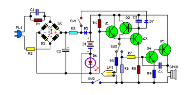
Safety measures are paramount in this design, given the direct connection to mains voltage. The circuit should only be handled with caution, and appropriate enclosures must be utilized to prevent accidental contact with high-voltage components. Overall, this circuit represents a practical solution for emergency lighting and alarm systems, combining efficiency, functionality, and safety in its design.This circuit is permanently plugged into a mains socket and NI-CD batteries are trickle-charged. When a power outage occurs, the lamp automatically illuminates. Instead of illuminating a lamp, an alarm sounder can be chosen. When power supply is restored, the lamp or the alarm is switched-off. A switch provides a latch-up function, in order to extend lamp or alarm operation even when power is restored. Mains voltage is reduced to about 12V DC at C2`s terminals, by means of the reactance of C1 and the diode bridge (D1-D4). This avoids the use of a mains transformer. Trickle-charging current for the battery B1 is provided by the series resistor R3, D5 and the green LED D6 that also monitors the presence of mains supply and correct battery charging.
Q2 & Q3 form a self-latching pair that start operating when a power outage occurs. In this case, Q1 biasing becomes positive, so this transistor turns on the self latching pair. If SW3 is set as shown in the circuit diagram, the lamp illuminates via SW2, which is normally closed; if set the other way, a square wave audio frequency generator formed by Q4, Q5 and related components is activated, driving the loudspeaker. Warning! The circuit is connected to 230Vac mains, then some parts in the circuit board are subjected to lethal potential!.
Avoid touching the circuit when plugged and enclose it in a plastic box. 🔗 External reference
Related Circuits
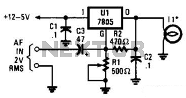
In the visible-light transmitter, a 7805 voltage regulator is configured in a variable-voltage setup, with an audio signal input to modulate the output voltage. The modulated output voltage is utilized to transmit information through an incandescent lamp. The visible-light transmitter...
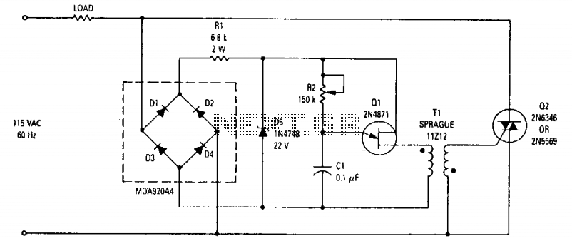
This wide-range light dimmer circuit utilizes a unijunction transistor and a pulse transformer to implement phase control for the TRIAC. The circuit is designed to operate from a 115-volt, 60 Hz power source and can manage up to 800...

A common piezoelectric alarm, such as the Murata PKB5-3A, possesses many valuable attributes, including compactness, lightweight design, efficiency, and reliability. However, the loud, high-pitched sound output can be irritating in many applications. The circuit provided transforms this buzzer into...

This circuit is a real core of the dimmer system. This circuit generates a ramp 100 Hz signal which is synchronized to the incoming mains voltage. The ramp signal which is generated will start from 10V and go linearly...

Four way Traffic light controller which Has Red, Yellow and Green LEDS. It uses the AT89C2051. The four-way traffic light controller is an essential electronic system designed to manage traffic flow at intersections by controlling the operation of Red, Yellow,...
This circuit is a wireless car alarm system composed of two modules: a transmitter and a receiver. It operates using FM radio waves and is compatible with vehicles that have a 6-12V DC power supply. If the vehicle's power...