
Enlarging Light Meter Circuit
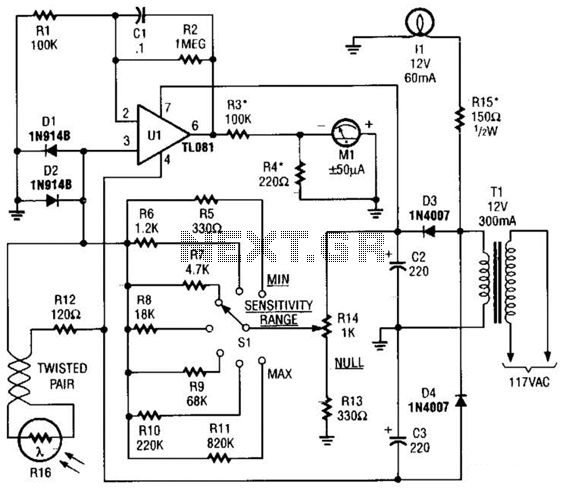
A variable positive current, determined by the settings of R14 and S1, is derived from the positive supply rail and also fed to pin 3 of Ul. When the two currents, which have opposite polarities, are equal, they cancel each other out, resulting in no current applied to pin 3 of Ul. Consequently, the output of Ul becomes zero, and meter Ml registers accordingly, indicating a null. However, when light strikes R16 and its resistance decreases, the current through the device increases, making the negative current greater than the positive current. This causes the output of Ul to swing negative, leading the pointer to move in the negative direction, indicating that the light intensity must be reduced by using a smaller lens opening on the enlarger (smaller f-stop). Conversely, if the light is too dim, the opposite occurs. Lamp L1, a 12-V 60-mA grain of wheat unit, illuminates the meter scale, while R15 limits the meter's illumination to a faint glow, ensuring the face of Ml is visible in a photo darkroom. Resistors R3 and R4 should be selected based on the meter used. With a dual supply of +/-12 V, Ul produces an output voltage of 10 V peak-to-peak. The resistance of R3 can be calculated by dividing the peak voltage (10/2) by the full-scale meter current (in amps); thus, R3 = (10/2)/0.0005 = 100,000 ohms. R4, the shunt resistor, should be selected to match the meter's internal resistance.
The described circuit utilizes a TL081 FET operational amplifier, which is ideal for low-noise applications due to its high input impedance and low bias current. The configuration allows for precise control over the gain and bandwidth, ensuring accurate readings from the D'Arsonval meter. The LDR's integration into the circuit enables real-time light intensity measurement, which is critical in applications such as photographic darkrooms where light levels must be carefully controlled.
The dual-polarity power supply design is essential for providing the necessary voltage levels to the op-amp and ensuring that the meter can accurately reflect both positive and negative deviations from the null point. The selection of resistors R3 and R4 is crucial for calibration, as R3 must be calculated based on the specific characteristics of the meter movement to ensure that it operates within its specified current range. R4's value should match the meter's internal resistance to prevent loading effects that could distort the readings.
The use of a variable positive current through R14 and S1 allows for dynamic adjustments based on the light conditions, providing flexibility in operation. The system's feedback mechanism, which relies on the balance of currents at pin 3 of Ul, forms the core of its functionality, enabling it to indicate whether adjustments to the light intensity are necessary. This feedback loop, combined with the visual indicator provided by the illuminated meter scale, ensures that users can make informed decisions regarding exposure settings in photographic processes. Meter Ml, a +/-50-uA zero-center D`Arsonval meter movement is driven by Ul, a TL081 FET op amp, through R3. The gain of Ul is set at 11 by Rl and R2, while capacitor 01 is used to restrict the bandwidth of Ul to 1.6 Hz.
Power for the circuit is derived from a simple dual-polarity 12- V power supply (consisting of Tl, D3, D4, 02, and 03). A light-dependent resistor (LDR), R16 (which is a semiconductor element whose resistance decreases as it is exposed to increasing illumination), is used as a light-sensing device.
One end of R16 is connected to the negative supply rail through R12, arid the other end is connected to pin 3 of Ul, applying a negative current to Ul. A variable (over a 4:1 range) positive current determined by the settings of R14 and Si (and derived from the positive supply rail) is also fed to pin 3 of Ul. When the two currents (of opposite polarities) are equal, they cancel each other out, so effectively no current is applied to pin 3 of Ul.
With no current applied to pin 3, the output of Ul is zero and meter Ml registers accordingly, indicating a null. However, when light striking R16 causes its resistance to decrease, the current through the device increases, making the negative current greater than the positive current.
Under that condition, the negative current causes the output of Ul to swing negative, causing the pointer to swing in the negative direction. That indicates that the light intensity must be reduced by using a smaller lens opening on the en-larger (smaller f/stop).
The opposite occurs if the light is too dim. Lamp 11, a 12-V 60-mA grain of wheat unit, is used to illuminate the meter scale, and R15 is used to limit the meter`s illumination to a faint glow that is just blight enough so that the face of Ml can be plainly seen in a photo darkroom. Resistors R3 and R4 should be selected for the meter used. With a dual supply of +/-12 V, Ul produces an output voltage of 10 V peak-to-peak. The resistance of R3 can be found by dividing the peak voltage (i.e., 10/2) by the full-scale meter current (in amps); i.e., R:] = (10/2)/0.0005 = 100,000 .
R4, the shunt resistor, should be selected to have a value equal to Hie meter`s internal resistance. 🔗 External reference
Related Circuits
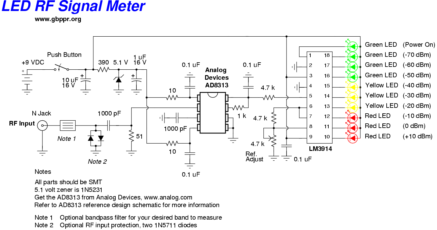
This RF Wave Absorption meter detects signals from 10 centimeters to 10 meters, depending on the setting of the 22 MegOhm gain adjustment potentiometer and the transmitter power. The RF signal is captured through germanium OA91 diodes and rectified...
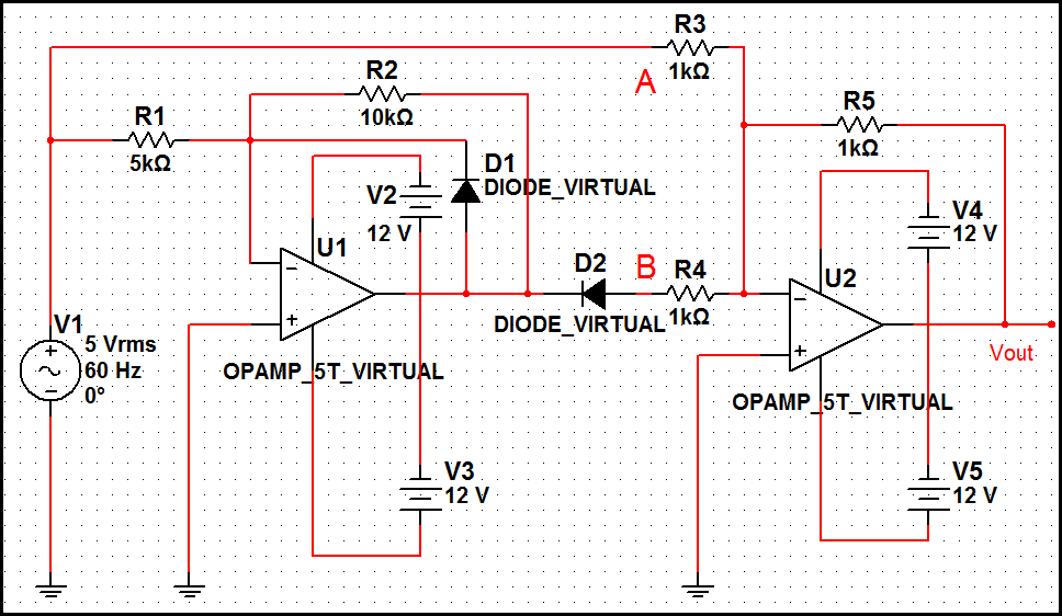
The optimal operational amplifier circuit used to convert a sine waveform into a rectangular waveform is the Schmitt trigger circuit. The Schmitt trigger circuit is a vital component in signal processing, particularly for converting analog signals into digital signals. It...
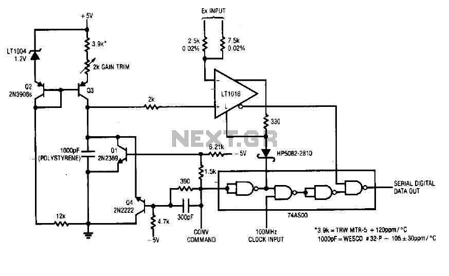
Each time a pulse is applied to the control input for conversion, Q1 resets the 1000 pF capacitor to 0 V. This resetting action takes 200 ns, after which the capacitor begins to charge linearly. In precisely 10 microseconds,...
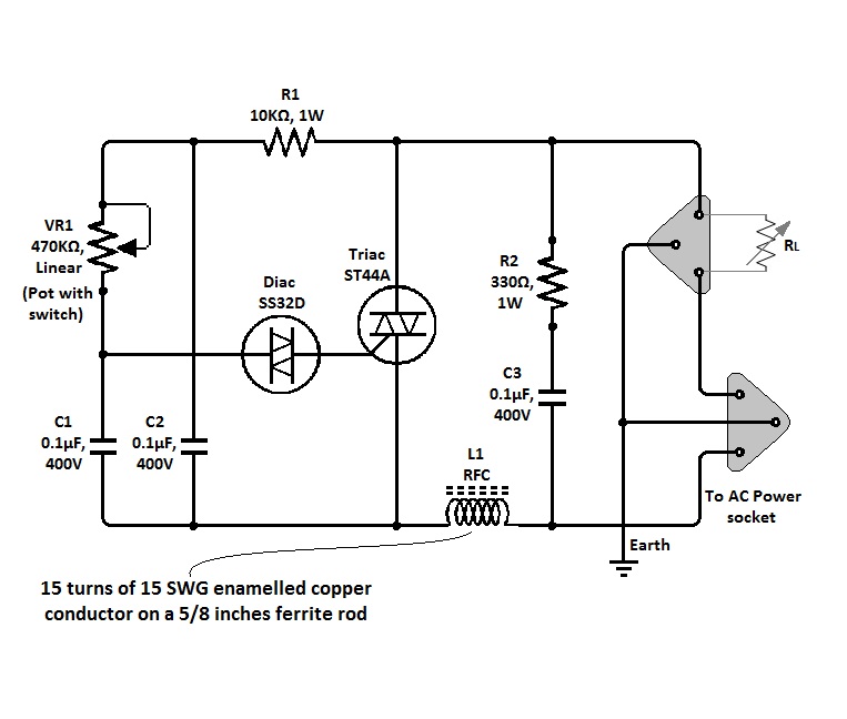
The circuit of a simple triac light dimmer can be used to dim incandescent lamps directly from AC mains. It is easy to construct and requires very few components. A potentiometer is utilized to control the load power or...
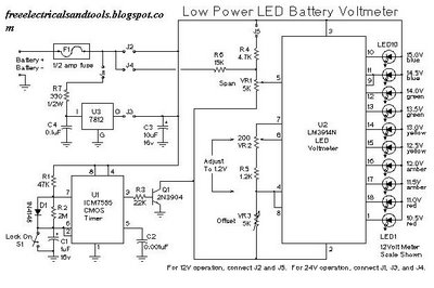
This is a low power voltmeter circuit designed for use with alternative energy systems that operate on 12V and 24V batteries. The voltmeter features an expanded scale that indicates small voltage steps within the 10 to 16 volt range...
A circuit diagram for an animal repeller is provided. The circuit has been developed but is not functioning as intended. Assistance is requested for troubleshooting. The animal repeller circuit typically employs ultrasonic sound waves to deter animals from specific areas....
Warning: include(partials/cookie-banner.php): Failed to open stream: Permission denied in /var/www/html/nextgr/view-circuit.php on line 713
Warning: include(): Failed opening 'partials/cookie-banner.php' for inclusion (include_path='.:/usr/share/php') in /var/www/html/nextgr/view-circuit.php on line 713