
VHF Overtone Oscillator
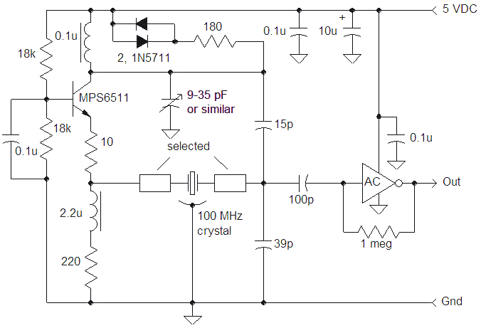
The VHF overtone oscillator circuit described is designed to effectively utilize overtone crystals by employing a tuned tank circuit that allows for precise frequency selection. The use of a trimmer capacitor or variable inductor enables fine-tuning to achieve the desired oscillation frequency, while the series capacitors create a low voltage output suitable for driving logic circuits. The implementation of Schottky diodes ensures that the transistor remains in a linear operating region, preventing distortion in the output signal.
The circuit's design emphasizes stability and ease of adjustments, with provisions for both fixed and variable tuning options. The inclusion of a grounded-base configuration with a series emitter resistor enhances the stability of the transistor operation, while the careful selection of components ensures compatibility with various logic devices. The PCB layout is optimized for traceability and effective grounding, promoting reliable operation in practical applications.
This oscillator circuit can be employed in various applications requiring stable VHF signals, such as communication systems, signal generators, and other electronic devices that rely on precise frequency generation. The careful selection of components and design considerations ensures that the circuit can accommodate the inherent complexities of VHF overtone crystals, making it a versatile solution for high-frequency applications.VHF overtone crystals can be difficult to use due to the many frequencies at which the crystal is perfectly happy to oscillate. A typical 100 MHz, 5th-overtone crystal will oscillate at approximately 20 MHz, 60 MHz, 100 MHz, and even 140 MHz, not to mention other, unintended modes that such crystals often have.
Most VHF overtone oscillators use some sort of tuned circuit or frequency selective filter to select the desired mode and reject the other, equally active modes. The oscillator circuit shown below uses a simple tuned circuit to select the desired mode and is suitable for VHF crystals, including high overtone types.
A tank circuit in the collector of the exciter transistor is tuned to the desired crystal resonance, either by a trimmer capacitor as shown in the schematic or by a variable inductor in place of the 0. 1 uH. The frequency of the tank is determined by the 0. 1 uH choke, the parallel 9-35 pF trimmer capacitor, the series combination of the 15 pF and 39 pF capacitor and the reactance of the collector of the transistor and other stray reactance.
The 15 pF and 39 pF provide a low voltage "tap" for driving the crystal and the output buffer. In practice, the two selected components in series with the crystal would be replaced with jumpers and the tank would be peaked for maximum signal on the 39 pF, observed with a very low capacitance probe. Alternately, the trimmer may be set to the middle point between the extremes where oscillation stops by observing the output of the gate.
Once the optimum tuning is achieved, selected components are added in series with the crystal to center the frequency. Either jumper position may be used for fixed tuning or a mechanical trimmer could be added on one side and an additional selected component could center the tuning range.
Splitting the tuning to both sides of the crystal in this manner reduced the voltage levels due to these reactances. Adding inductance in either position will lower the frequency and adding capacitance will raise the frequency.
For applications where a fixed value is selected to center the frequency at design time, the frequency may be adjusted for individual crystals by adjusting the tank tuning, as long as the tuning doesn`t get close to the point where oscillation stops. The two schottky diodes in series with the 180 ohm resistor limit the signal swing at the collector, keeping the transistor in a linear range.
The resistor tends to remove the diodes` capacitive contribution to the tank which can cause start-up problems. The smaller signal at the 39 pF should be adequate for directly driving fast CMOS logic as shown, without overdriving the input of some "Tiny Logic" types that don`t have the robust limiting diodes that AC has.
The schematic shows the output directly from an AC gate, typically a 74AC04, but a 50 ohm resistor in series with a 0. 1 uF capacitor could be added in series with the output for driving 50 ohm loads. Check the specification of the chosen logic device to determine its load capabilities. The MPS6511 is a relatively fast transistor but many types will suffice. A 10 ohm resistor is added in series with the emitter to help stabilize the grounded-base circuit. Large, leaded components were used to make it easier to trace the circuit. Parts are soldered to little "islands" of pcb material on a tinned copper-clad ground plane. A pcb SMT carrier board holds the 74AC00 gate (I didn`t have a 74AC04 handy, so I tied one input of a NAND gate high to make an inverter).
Only one input of one of the gates is used and the other input is tied to the positive supply. All the other gate inputs are grounded. The output of the gate drives the 49. 9 ohm resistor and 68 pF capacitor that would connect to 50 ohm coax. The crystal is a 100 MHz, 5th-overtone AT-cut manufactured by Croven Crystals. The circuit adjusts smoothly with a nice peak in amplitude without jumps or sudden dying except wh 🔗 External reference
Related Circuits
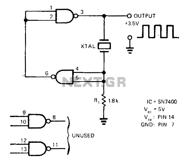
A SN7400 quartz crystal and a resistor provide a square-wave output of approximately 3.5 V. The circuit operates reliably at frequencies from 120 kHz to 4 MHz. The circuit utilizes a SN7400 integrated circuit, which is a quad two-input NAND...
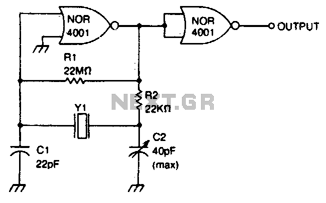
This circuit operates within a frequency range of 0 MHz to 2 MHz. The frequency can be finely adjusted to a specific value using the trimmer capacitor C2. Additionally, the second NOR gate functions as an output buffer. The circuit...
A tone generator operates on as little as 1.5 VDC using the Sallen-Key configuration. The tone generator will be applied to implement a phantom-powered signal source for testing balanced microphone inputs. Textbooks and web pages typically depict the Wien...

A simulation of a Colpitts Oscillator circuit using an NPN transistor and other components available in SimElectronics is presented. The feedback ratio is determined by the relative values of the capacitors C1 and C2. The frequency of oscillation is...
An attempt has been made to follow an instructable for some time; however, understanding its schematic remains challenging. The issue is not a lack of knowledge regarding the symbols used. In electronic schematics, symbols represent various components and their connections...
This circuit was featured in the "design ideas" section of EDN's March 5, 2007 issue. It is a relatively simple circuit that allows investigation into how the inductance of a toroid (or any core) is affected by saturation, which...