
AD574A unipolar and bipolar input circuit b
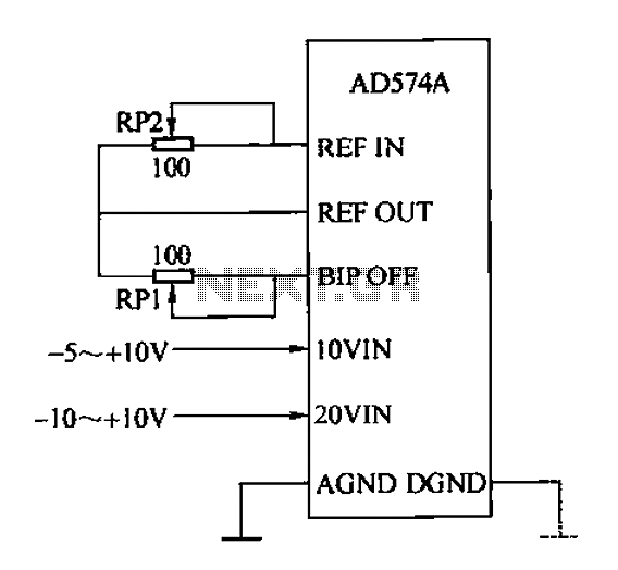
The AD574A A/D converter operates by converting an analog input signal into a digital representation with a resolution of 12 bits. This level of precision is suitable for various applications, including industrial automation, data acquisition systems, and instrumentation. The device can handle two types of input signals: unipolar and bipolar, making it versatile for different operational requirements.
For unipolar applications, the converter accepts voltage levels ranging from 0V to 10V or 0V to 20V. In this configuration, it is essential to ensure that the BIP OFF termination is set to 0V to avoid erroneous readings. The circuit design includes a 100nF capacitor for electrical grounding, which helps to stabilize the input signal and filter out noise. The resistor RP1 serves a crucial role in providing a zero adjustment, allowing for calibration of the output to ensure accurate digital representation.
In bipolar mode, the AD574A can accommodate input voltages of ±5V or ±10V. The BIP OFF termination voltage is adjusted to +10V, facilitating the conversion of negative voltage signals. The circuit design in this mode connects the BIP OFF end through a 1000Ω resistor (RP2) to the reference voltage, ensuring that the converter can accurately interpret both positive and negative voltage levels. This configuration is particularly useful in applications where the signal may swing above and below ground, such as in audio processing or sensor data acquisition.
Overall, the AD574A's flexible input configurations and high-resolution capabilities make it a valuable component in modern electronic systems, providing reliable data conversion for a wide range of applications. Proper circuit design and component selection are critical to maximizing the performance and accuracy of the A/D conversion process.AD574A is a high performance 12-bit successive approximation. A/D converter can be directly with the 8 or 16-bit microprocessor bus interface. Input into AD574A analog voltage, either unipolar or may be bipolar. Unipolar analog input voltage range of O-lOV or 0-20V} bipolar input voltage range is 5v or 20V. When unipolar input should BIP OFF Termination ov. A circuit connection shown in FIG. Figure BIP OFF side through the 100n electrical grounding resistance by RP1 can also be zero adjustment. When bipolar input, BIP OFF + lov termination voltage, circuit connection shown in Figure b. Circuit BIP OFF end by 1000 and the resistor RP2 REF, OU end rhyme + 10V voltage connections
Related Circuits
This 1 Hz and 2 Hz generator or oscillator is constructed using a 4060 IC as the oscillator and a 14-bit counter. To achieve a 1 Hz signal from the 4060, a 1/2 4013 flip-flop is utilized. This circuit...
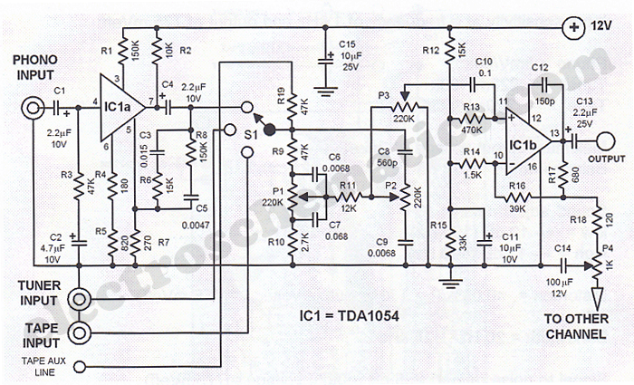
This Hi-Fi stereo preamplifier circuit is designed using the TDA1054 integrated circuit from SGS. The TDA1054 is a 16-pin DIL package that incorporates two separate preamplifier circuits. It is a low-noise preamplifier with minimal complications in the design process....
The circuit depicted is designed to protect a system from power supplies that may exceed safe limits. An example of this is small consumer products that utilize external AC adapters, where there is a risk of accidentally connecting the...
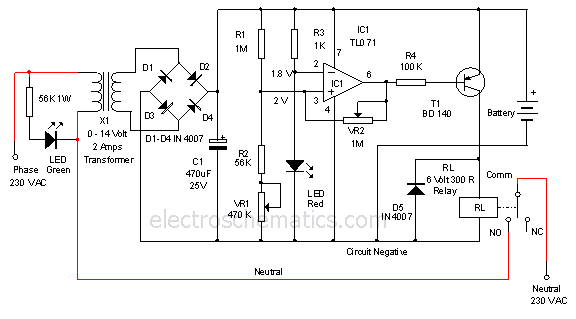
This is a 12-volt lead-acid automatic battery charger that stops the charging process once the battery reaches a full charge. This feature prevents overcharging. The 12-volt lead-acid automatic battery charger is designed to efficiently charge lead-acid batteries while ensuring safety...
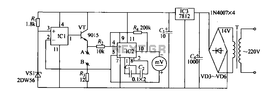
The contact resistance measuring circuit is illustrated in the figure. It primarily consists of a constant current circuit and an amplifying circuit. Operational amplifier IC1 is configured as a voltage follower, and the voltage across the load equates to...
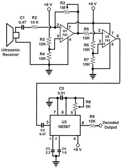
The ultrasonic receiver utilized in this circuit is specifically designed to vibrate optimally at a frequency of approximately 40 kHz. Consequently, the transmitter associated with this receiver must also emit waves at 40 kHz. When these waves interact with...
Warning: include(partials/cookie-banner.php): Failed to open stream: Permission denied in /var/www/html/nextgr/view-circuit.php on line 713
Warning: include(): Failed opening 'partials/cookie-banner.php' for inclusion (include_path='.:/usr/share/php') in /var/www/html/nextgr/view-circuit.php on line 713