
EQG MOD FOR DIRECT STEPPER MOTOR ACCESS

The circuit modification involves a systematic approach to enhance the control of the stepper motors in a mount system. The integration of the 74HC157 multiplexer is pivotal, as it facilitates the switching of serial signals between the hand controller and the PC. This is essential for ensuring that the user can effectively manage the motor commands without the risk of sending erroneous signals that could lead to equipment damage.
The choice of the 74HC157 is significant due to its capability to handle multiple inputs and outputs, allowing for seamless communication between different components of the system. The external SPST toggle switch provides an intuitive method for users to select the desired operational mode, enhancing user experience and control.
When implementing this modification, careful attention to detail is paramount. The specified tap points and cut patterns on the PCB must be followed precisely to ensure proper functionality. It is recommended to utilize a continuity tester to verify connections and ensure that all modifications align with the intended design.
Furthermore, the precautions regarding static electricity are critical, particularly when handling the CMOS components. Proper grounding techniques should be employed to mitigate the risk of damage during installation.
In summary, this modification not only enhances the functionality of the mount's stepper motors but also emphasizes the importance of careful installation and testing procedures to prevent potential issues during operation.The modifications involve direct access to the stepper motor controls of your mount. Any "mis-control" or "mis-command" / "invalid parameter" or "garbage" data sent to the mount could accidentally activate the stepper motors and allow it to rotate "freely" damaging any equipment connected to your mount. It is also possible that any garbage or invalid data sent to the mount could cause its firmware to generate mis-steps pulse sequences to the motors causing it to overheat. Make sure that you perform the modifications and testing while there is no physical "load" or dangling wires on your mount.
Be sure to disconnect the power once this event happens or if you notice any unusual sound coming from the motor assembly. The modification allows the user to control the mount`s stepper motor board via the PC`s serial connector.
The mod is implemented on the handcontroller utilizing the existing RJ11 PC serial interface connector and its built-in RS232C to TTL level converter. This will avoid any external circuit required to connect the mount`s DB9 TTL level connector to the PC`s serial port.
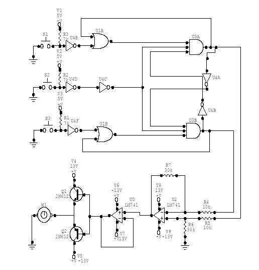
The mod circuit utilizes a Quad 2-1 Multipexer 74HC157 (Figure 2) that switches serial signals between the PIC controller of the paddle and the mount and PC. The mode of operation is set through an external SPST toggle switch; Below is a diagram of the modification (Figure 3).
It shows the connections of the individual multiplexer component of the 74HC157 chip to the respective pinouts and tap markings of the handcontroller board. Also, pinout labels of the actual chip with respect to the circuit diagram is also shown. Use this as a reference in connecting the wires to the board. The tap points image (Figure 4) shows were to solder the wires as labeled in the circuit diagram. It also shows which part of the board patterns need to be cut. The power and ground line is obtained from the the output pin of the 7805 +5V voltage regulator (Tap point K and L).
Figure 4a shows the tap points for an "older version" of the controller. The only thing that is different from the newer version are the location of tap points "A" and "C". The other tap points and cut points are pretty much the same. If there are any differences then you may have to determine the actual tap/cut points yourself based on the circuit above (Figure 3). You may need to utilize a circuit continuity tester for this. 3. TRIM the pins of the 74HC157 (all 16 of them) and leave some length of the pin for the wires to be soldered on it.
Removing the excess part of each pin will allow you to piggyback the 74HC157 chip on top of the paddle`s PIC controller (the largest square IC on the paddle). Refer to Figure 5 for the actual chip mounting. Make sure that you dont touch any of the pins of the IC as this is a CMOS chip which is very sensitive to static electricity.
4. Using double adhesive tape, mount the 74HC157 chip on top of the PIC chip (refer to figure 5). Take note of the "PIN 1" orientation of the 74HC157 using the chip`s "notch" as a reference. 5. Using a sharp knife cutter (or any blunt tool), cut the indicated patterns on the PCB. Make sure that only the indicated patterns are cut and that you dont scratch the board patterns near the area. Fig 🔗 External reference
Related Circuits
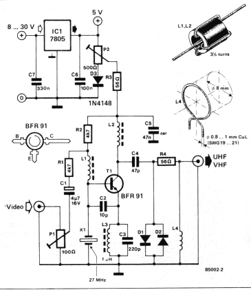
A TV modulator is really no more than a transmitter. It is a very small transmitter, admittedly, but none the less that is what it is. What does a modulator actually do? In general - and this design is...
Stepper motors are a recurring topic of interest. This circuit converts a clock signal from a square wave generator into signals that have a 90-degree phase difference, which are necessary for driving the stepper motor windings. The trade-off for...
This DC Motor Controller circuit will control a 12V dc motor. The system will have three pushbuttons: a START button, a REVERSE button and a STOP button. Initially, the motor must not be running. When the START button is...
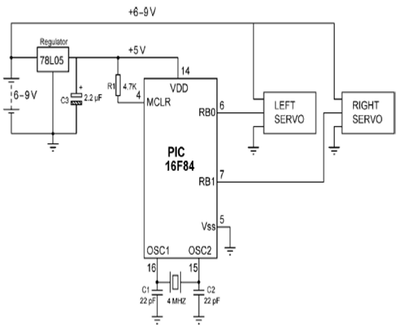
Mobile robots are utilized in various industrial, commercial, research, and hobby applications. This project focuses on controlling a mobile robot using servomotors. The robot is based on a well-known mobile robot called Boe Bot, developed by Parallax. The basic...
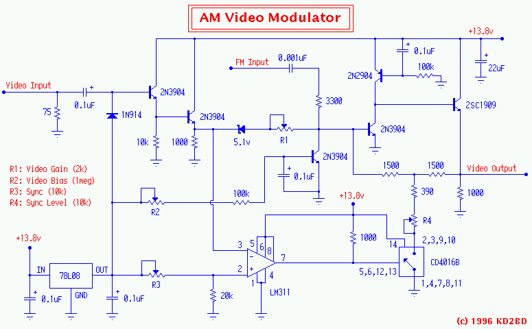
A 2N3904 in the base circuit sets the Q point of the amplifier. FM subcarrier audio at 4.5 MHz is also injected at this point through a 3300 ohm resistor and a DC blocking capacitor. A high frequency 5-watt...
The T5753 is a phase-locked loop (PLL) transmitter integrated circuit (IC) designed to meet the requirements of low-cost RF transmission systems, capable of operating at data rates of up to 32 kBaud. It supports a transmitting frequency range from...