
ESR Meter
The ESR Meter's design incorporates essential components and configurations to ensure accurate measurements of capacitor performance. The use of operational amplifiers provides the necessary signal amplification and processing, while the oscillator circuit enables the generation of a stable test frequency. The careful selection of resistors and capacitors allows for fine-tuning of the measurement parameters, ensuring that the device can accurately reflect changes in the capacitor's equivalent series resistance. The inclusion of protective diodes and discharge resistors safeguards the circuit from potential damage due to voltage spikes or incorrect connections, enhancing the reliability of the ESR Meter in various testing scenarios. Overall, this meticulous design allows technicians and engineers to maintain and assess the health of electrolytic capacitors effectively, ensuring optimal performance in electronic circuits.The ESR Meter is basically an AC Ohmmeter with special scales and protective circuitry. It provides a continuous reading of series resistance in electrolytic capacitors. It operates at 100 kHz to keep the capacitive reactance factor near zero. The remaining series resistance is due to the electrolyte between the capacitor plates and indicates the state of dryness. Capacitor termination problems also show up plainly due to the continuous ohmic reading. The ESR meter uses 8 operational ainplifiers. An op-amp is an idealized basic amplifier with two inputs. The non-inverting input (+) has an in-phase relationship with the op-amp output, and the inverting input (-) an out-of-phase relationship. Op-amps are usually used with negative feedback and reach a stable operating condition when their two inputs are equal in voltage.
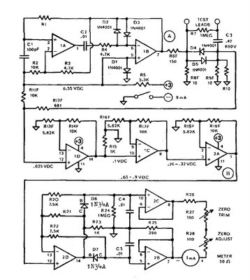
Op-amps IA & 1B form a regenerative 100 kHz oscillatnr circuit. Capacitor C1 is the basic tiining capacitor and RI is selected to set frequency. Diodes D2 & D3 clip the bottom and top of the output waveform so that the output level and frequency are resistant to battery voltage changes. The oscillator output of op-amp 1B drives 10-ohm source resistor R8F. The test-capacitor, thru the test leads, couples this 100 kllz signal to 10-ohm load resistor R9F. The amount of voltage developed here is indicative of the capacitors ESR value. (The 10-ohm resistors determine the basic iieter scaling. ) Capacitor C3 blocks any DC voltage present on the test-capacitor. Diodes D4 & D5 protect the ESR Meter from any initial charging current to C3. Resistor R7 discharges C3 after test. A DC operating bias of 0. 55 V is established by diode D1 for the oscillator stage and for all subsequent stages, which are DCcoupled and operated class A.
DC bias from D1 and ESR signal from R9F are combined at the input of op-amp 1D. Both voltages are amplified by 1D, 1C, & 2A. Each of these three stages has an amplification factor of about 2. 8 due to the ratio of output-voltage to feedback~voltage at the (-) input, which is determined -by feedback resistors R13F & R14F, etc. Op-amp 2D is configured as a peak-to-peak detector. when the in-corning AC signal goes more positive than the normal bias level of about 0. 77 Volt, the output of 2D also goes positive. But it must go positive enough to overcome the voltage drop across diode D6 before a fully equalizing positive voltage can be fed back to the -(-) input thru R20 to stabilize the op-amp.
-Capacitor C4 is charged to the peak value of the AC signal and accurately represents the peak of the incoming AC signal. The voltage drop across the diode becomes almost inconsequential due to the feedback process, and the circuit works down to a few mV.
Resistor R21 provides a constant minimum amount of negative feed-back around op-amp 2D. The negative feedback increases the op-amp bandwidth which, most importantly, keeps the amplifier input-to-output phase-shift low enough for proper circuit operation. The two outputs from the peak-to-peak detector are connected to two high-input-impedance unity-gain DC amplifiers, which drive the 1 mA meter movement differentially.
🔗 External reference
Related Circuits
The tachometer, also known as a revolution counter, is an instrument that measures the speed of rotating machinery, typically expressed in revolutions per minute (RPM). This project involves creating a custom sensor using a light-emitting diode (LED) as a...
Observe the left side of the circuit, which includes a sensing coil and an operational amplifier (op-amp). When connected as shown in the schematic, the circuit did not pick up any signals. A 1mH radial inductor was not available,...
Pulses are received by the timer from the distributor points. When the timer output is high, Meter M receives a calibrated current through R6. The meter does not... The circuit described involves a timer that receives pulse signals from distributor...

This digital thermometer circuit diagram utilizes a common 1N4148 diode as the temperature sensor. The diode's temperature coefficient of -2 mV/°C is leveraged to create an accurate electronic thermometer. A digital multimeter is employed to display the measured temperature,...
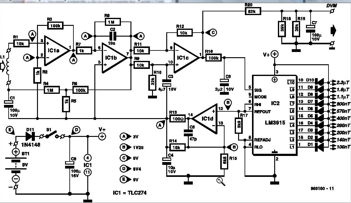
Some experts believe that static magnetic fields (SMFs) may affect the physical well-being of individuals. If one subscribes to this viewpoint, the magnetic-field meter described here will aid in locating sources of SMFs and assessing their strength. These results...
This is a circuit schematic diagram for VU meters. The circuit is controlled by the IC TL072 and follows a measurement circuit as per the National general application. The input circuit around IC1 is designed for adaptation and amplification...