
VU Meter using LM3915
The circuit schematic for the VU meter is designed to provide a visual representation of audio signal levels through LED indicators. The operational amplifier IC TL072 serves as the primary signal processing unit, providing necessary amplification and adaptation of the incoming audio signal. The trimmer resistor TR1 allows for fine-tuning of the gain, enabling users to adjust the sensitivity of the circuit according to the input signal strength.
The LM3915 is utilized for the visual display of the audio levels, configured to perform half-wave rectification of the input acoustic signal. This rectification process is crucial for converting the alternating current (AC) audio signal into a direct current (DC) signal that can be effectively measured and displayed by the LEDs.
The switch S1 is an important component that allows the user to select between different modes of indication. In this design, it specifically targets LED outputs, facilitating a clear visual representation of the audio levels. The circuit is capable of controlling up to 19 LED indicators, providing a granular display of signal levels.
Resistors R6 and R7 play a vital role in determining the input signal level, which is set at 7.8V. This configuration ensures that the operational amplifier IC1 operates within its optimal range, with a gain setting of one in the first stage. The design also specifies a 3 dB difference in level between LEDs D10 and D11, ensuring consistent and proportional visual feedback.
The power supply section of the circuit is designed to deliver adequate current to the LED indicators, preventing potential overload situations. This consideration is essential for maintaining the longevity of the LEDs and ensuring reliable operation of the VU meter circuit. Overall, this schematic provides a comprehensive solution for audio level visualization, integrating amplification, rectification, and LED indication in a cohesive design.This is a circuit schematic diagram for the VU meters. Circuit diagram is controlled by IC TL072. A measurement circuit according to the National general application. Around the input circuit IC1 to make adaptation and amplification of the trimmer TR1 [GAIN]. Around the circuit IC2 LM3915 makes a half-wave rectification of the acoustic signal. W ith the switch S1, we select the type of indication, that we will have the LED. Circuit diagram to control LED depat led 19 men. With the price of R6 and R7 resistance in the circuit, signal level, the entry is 7. 8V (IC1 gain first stage, is one), and the difference in level between LED D10-11, should be 3 db. Department of positive supply, should have the possibility to give more this time, one and it is overloaded with LED current. The following is a schematic drawing: 🔗 External reference
Related Circuits
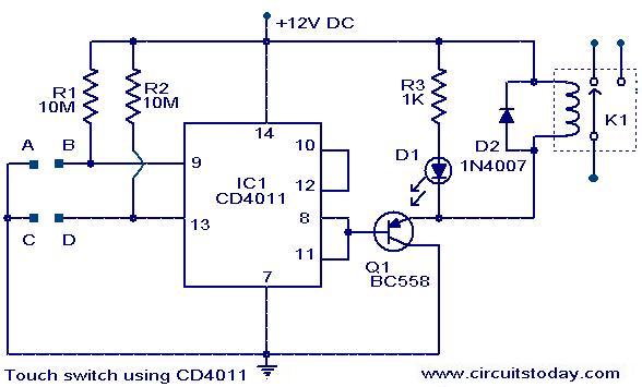
A simple touch switch circuit using the CD4011 is presented. The CD4011 integrated circuit (IC) is configured as a flip-flop. Pins 9 and 13 of the IC function as the set and reset terminals, respectively. CMOS ICs like the...

A very simple dimmer circuit with only the essentials. In this circuit, the values are given for a BT138 at 220V AC. For 115V AC, experimentation with values may be necessary. R1 can vary from one triac to another;...
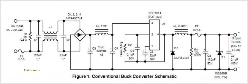
Quasi square wave resonant converters, also referred to as quasi resonant (QR) converters, facilitate the design of flyback Switch Mode Power Supplies (SMPS) with diminished Electro Magnetic Interference (EMI) and enhanced efficiency. Due to their low noise generation, QR...
This Hartley oscillator was constructed using a single 45 tube and is based on a design published in a 1932 QST article by George Grammer. The initial circuit experienced performance issues due to weak 45 tubes, necessitating a very...
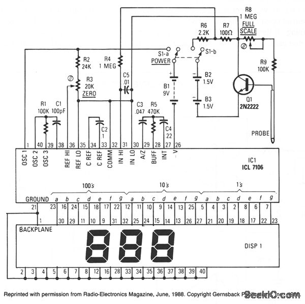
IC1, an Intersil ICL7106, comprises an A/D converter, a 3.5-digit LCD driver, a clock, a voltage reference, seven-segment decoders, and display drivers. An alternative component, the ICL7107, is suitable for driving seven-segment LEDs. The probe body consists of a...

This temperature meter utilizes the precision micro power centigrade sensor IC LM35. The output voltage of the IC is linearly proportional to 10 mV per degree centigrade. The LM35 temperature sensor is a versatile and widely used device in electronic...