
The Wooden Menace Circuit
The schematic for the robotic arm incorporates several key components that work together to facilitate its operation. The PIC microcontroller serves as the central processing unit, managing the signals sent to the servos based on input received from the PS1 controller. Each servo motor, which is responsible for the arm's movement, requires a dedicated signal line from the PIC to control its position through Pulse Width Modulation (PWM).
The power supply design is critical for ensuring stable operation. The 9V battery is the primary power source, and the LM7805 voltage regulator steps down this voltage to a stable 5V, which is necessary for the PIC and the servos. The inclusion of a 1µF capacitor at the output of the LM7805 is essential for filtering and smoothing the output voltage, minimizing fluctuations that could affect performance.
The RJ45 connector facilitates communication between the robotic arm and the controller. The choice of this connector is practical, as it allows for a secure and reliable connection. The pull-up resistor maintains the signal line at a high state when not actively driven low, ensuring that the microcontroller remains in a ready state for input.
The reset functionality is a crucial aspect of the design. Pin 1's role as a reset pin allows for the microcontroller to restart when necessary, providing a method to clear any potential errors or undesired states. By tying this pin high, the design avoids the need for a physical reset button, simplifying the user interface while ensuring the system remains operational at all times.
Overall, the schematic design for the robotic arm integrates these components effectively, allowing for precise control of the arm's movements through the user-friendly interface of the PS1 controller. The careful consideration of power management, signal integrity, and reset functionality contributes to the robustness and reliability of the robotic arm's operation.The hardware schematic for the wooden menace (robotic arm) is fairly straight forward. The PIC microcontroller has one control line feeding to each servo and it also connects to the RJ45 connecter. The RJ45 connector is used for getting input from the controller. The power circuit is just a 9v Battery hooked up to the LM7805 with a 1uF capacitor hooked to output & ground of the LM7805 to keep a steady 5v DC. Each servo has 3 wires coming out of it. Power, Ground & Signal(PWM). Power & Ground are tied directly to our 6v source. Each signal pin from each servo is tied to a unique pin on the PIC as seen on the schematic. This project uses a [fake] ps1 controller to remotely control the robotic arm. The female RJ45 connector is used & mounted onto the robotic arm awaiting the male RJ45 connection from the controller. This is tied high (logic 1; +5v) once again using a pull-up resistor. Pin 1 is effectively a reset pin. The PIC will restart-Memory Clear-when this pin is low (logic 0, +0v). For this project I did not include a reset button so I just have the pin tied high always, so the PIC will always be running as long as it is powered.
🔗 External reference
Related Circuits
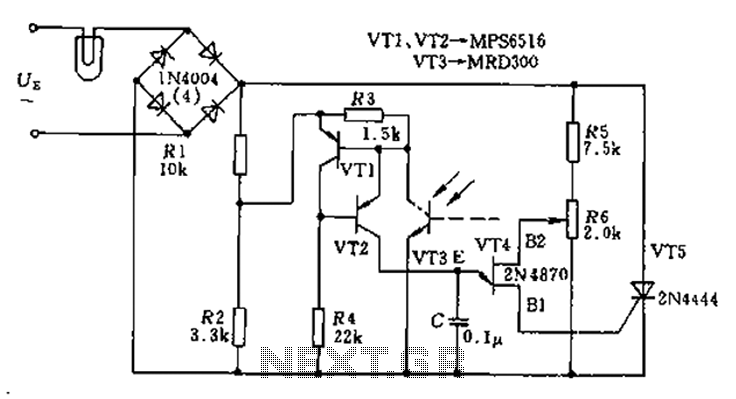
The circuit utilizes a thyristor-based AC automatic voltage regulator to stabilize the brightness of lamp L. A diagonal line connects the thyristor to the T5 bridge. The trigger pulse for the thyristor is generated by a single-junction transistor, VT4....
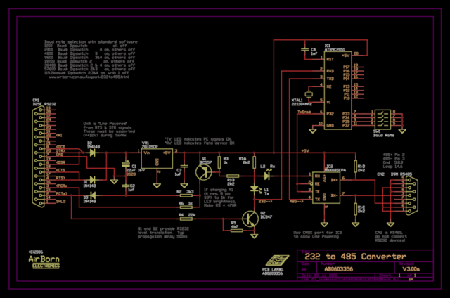
The new version of the RS485 interface addresses the issues associated with RTS control, which was a challenge in the previous design. However, implementing this solution requires a microprocessor, adding complexity to the design. This unit is currently being...

Input 1 functions as a gating period, during which a single rising edge on input 2 produces a logic 1 output. Any other input that indicates non-identical frequencies results in a logic 0 output. IC1a converts input 1 into...
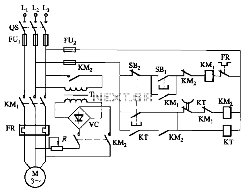
The circuit depicted in Figure 3-135 employs a time relay (KT) to determine the braking time. The circuit utilizes a time relay, which is a crucial component for controlling the duration of the braking process. The time relay KT is...
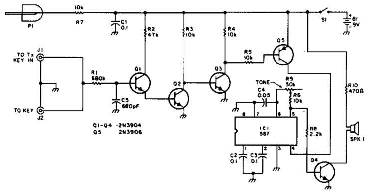
For use with low-power transmitters that require a positive keying voltage. The transistors Q1, Q2, and Q3 are configured as a switching amplifier. When the key is pressed, the collector of Q3 is pulled to ground, which activates Q5...
Assistance is needed in analyzing a circuit, specifically regarding the frequency cut-off between the bass and treble channels. The potential cut-off frequencies under consideration are 500Hz, 1KHz, or 5KHz. In audio processing circuits, the frequency cut-off point between bass and...