
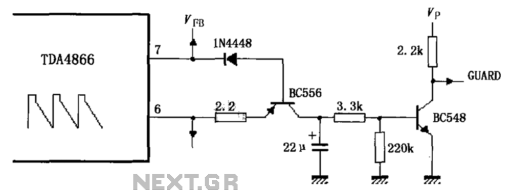
External protection signal generator by a circuit diagram TDA4866
The TDA4866 circuit is designed to ensure the integrity and reliability of the signal generation process through its dual-layer protection mechanism. The external signal generator circuit protection serves as a primary defense against potential signal anomalies or external disturbances that may affect the overall operation. The internal protection circuit is tasked with monitoring and controlling the performance of the system, ensuring that any deviations from expected operational parameters are promptly addressed.
The BC556 transistor plays a crucial role in amplifying the output signal during normal conditions. When the vertical amplitude of the output signal is within the acceptable range, the BC556 is activated, allowing for efficient signal amplification. The BC548 transistor, meanwhile, functions as a low-level output indicator, providing a visual or electronic cue to the system's operational status. This transistor is designed to turn on when the base current is sufficient, indicating that the system is functioning as intended.
In scenarios where the circuit encounters issues, the behavior of the transistors changes significantly. A drop in the vertical amplitude of the output signal signifies a malfunction, prompting the BC556 transistor to deactivate. This action is critical as it prevents further amplification of a potentially faulty signal. Simultaneously, the lack of base current to the BC548 transistor causes it to turn off, resulting in a high output signal that serves as an error indication. This dual response mechanism is vital for maintaining the reliability of the circuit and preventing damage due to uncontrolled conditions.
The design of the TDA4866 circuit, with its integrated protection features and transistor-based signaling, exemplifies a robust approach to signal management in electronic systems. The careful interplay between the BC556 and BC548 transistors ensures that the circuit can both amplify and indicate operational status effectively, providing essential feedback for troubleshooting and maintenance. As shown in FIG TDA4866 constituted by an external signal generator circuit protection. The role of the internal protection circuit is out of control, the external protection c ircuit functions. Vertical amplitude of the output signal during normal operation of a larger, BC556 transistor is turned on, while the base current of transistor BC548 get too turned on to work as a low-level output indication. When not working properly, the vertical amplitude of the output signal is low, transistor BC556 is turned off, while transistor BC548 no base current is turned off, the output is high as an error work instructions.
Related Circuits
The Audio Automatic Gain Control (AGC) circuit monitors the output signal level of an audio preamplifier. When the input signal increases, the AGC circuit automatically reduces the amplifier's gain. Conversely, when the input signal decreases, the AGC circuit increases...
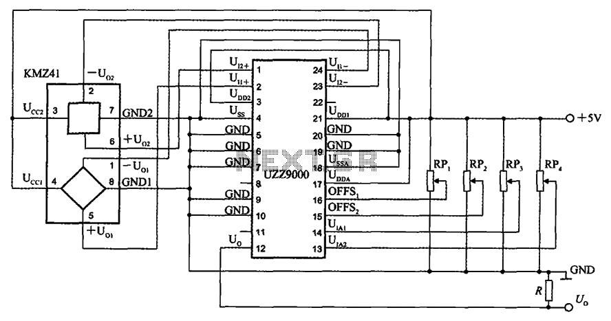
The UZZ9000 KMZ41 detection circuit is configured based on the voltage output type and angle. It operates with a +5V power supply. Potentiometers RP1 and RP2 are used for offset voltage adjustment, while potentiometers RP3 and RP4 are utilized...
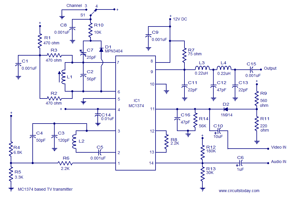
A simple TV transmitter circuit utilizing the TV modulator circuit IC MC1374. It operates with a 12V supply and is capable of broadcasting on channel 3 or 4, employing FM modulation for sound transmission. The TV transmitter circuit based on...

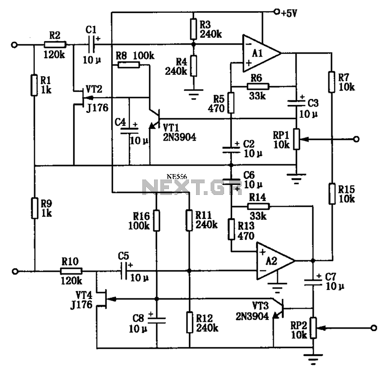
The circuit operates by processing an input signal through IC1-1 and a fourth-order low-pass filter, which provides a slope of 24 dB/octave with a cutoff frequency (fc) of 70 Hz and an amplification of 8.2 dB. The output from...
The primary goal of this project is to utilize 555 timers to detect motion in the surrounding environment. The output of this circuit will activate an LED and produce an audible sound similar to an alarm. The circuit design employs...
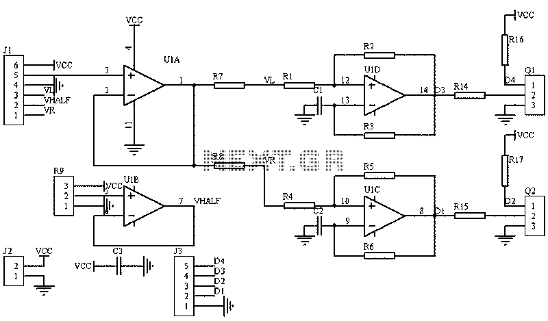
The image illustrates a circuit that utilizes a linear potentiometer (or linear Hall element) to control the PWM generation for two chassis drive motors in a gamepad or joystick used in model aircraft. J1 represents the handle of the...