
External wiring diagram of PLC

The described PLC system is designed to manage a complex automation task involving multiple input and output signals. The input signal path is structured to allow for seamless operation of the motor starter button and photoelectric switches, which are critical for detecting the presence of objects or the completion of tasks at various stations. The normally open contacts of the photoelectric switches ensure that the system remains inactive until triggered by an object, enhancing safety and efficiency.
The 18 output channels of the PLC facilitate control over various components, including motors and solenoids. The use of solid-state relays for driving AC contactors and inductive loads is a significant design choice, as it mitigates the risk of voltage spikes that could otherwise disrupt the PLC's operation. This isolation is crucial for maintaining the integrity of the control system and ensuring that the PLC can operate reliably in an industrial environment.
The Mitsubishi FX2N-48MR-O01 PLC is well-suited for this application, offering ample I/O capabilities and robust performance. The external wiring configuration, which includes specific designations for each control point, is essential for troubleshooting and maintenance. Each component, from the motor start button to the limit switches, is strategically placed to optimize the workflow of the robotic glazing process.
In summary, this PLC-based control system integrates various sensors and actuators to automate the glazing process efficiently. The careful consideration of input and output management, along with the use of solid-state relays for isolation, highlights the system's reliability and effectiveness in an industrial setting.1/0 defined PLC Table. Its input signal path 13, including: 1 motor starter button. 2, 3, 5, 7, 8, 9 station photoelectric switch normally open contact, move the CD machine 37 and 7 of the cylinder upper and lower limit switch, and spraying is completed and the response signal SF greenware position signal ARP. Output PLC has 18 road, including: 1 ~ 9 9 station motor control signal, transfer machine 37 and 7 CD rise and fall Yan electromagnetic control signal, transfer machine 37 and 7 CD motor control signal, the clamp solenoid control signal, and greenware position signal RI, and answering spraying Ends completion signal ASF.
Output control signals YO-Y17 is no direct drive AC contactor or solenoid valve, but is driven by solid state relays, so it will be PLC output interface circuit AC contactor or inductive loads such as solenoid valves to isolate, avoid the coil off current moment generated on PLC affected. The robot glazing peripheral device control system input and output points require control requirements, the system used Mitsubishi FX2N- 48MR-O01 type PLC.
Its external wiring circle tSB1 1 motor start button, SG1-SG6 were 2, 3, 5, 7, 8, 9 stations on the motor trip switch. soi and SQ2 for the transfer machine 37 cylinder upper and lower limit switch, SQ3 and SQ4 to transfer machine 7, cylinder soil bit and lower limit switch.
Related Circuits
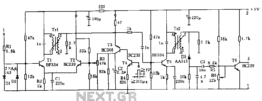
The circuit operates at a voltage of 9V with a current consumption of only 5mA. It allows for frequency adjustment within the range of 150 to 180 kHz, featuring a bandwidth of approximately 20 kHz. This configuration ensures that...
%2BCircuit%2Bdiagram%2Busing%2BCD4047%2Band%2BIRFZ44%2Bpower%2BMOSFET.png)
This simple low-power DC to AC inverter circuit converts 12V DC to either 230V or 110V AC. By making simple modifications, it is also possible to convert 6V DC to 230V AC or 110V AC. This inverter can be...
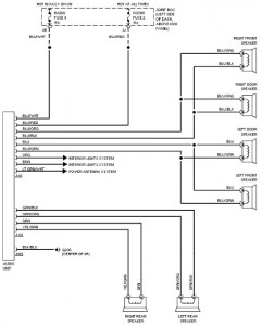
The following document provides a comprehensive car wiring diagram for the 1994 Mazda 626. It includes diagrams for the 2.0L and 2.5L engine configurations, covering the A/C circuit, heater circuit, anti-lock brake circuits, and anti-theft circuit. The wiring schematic for...
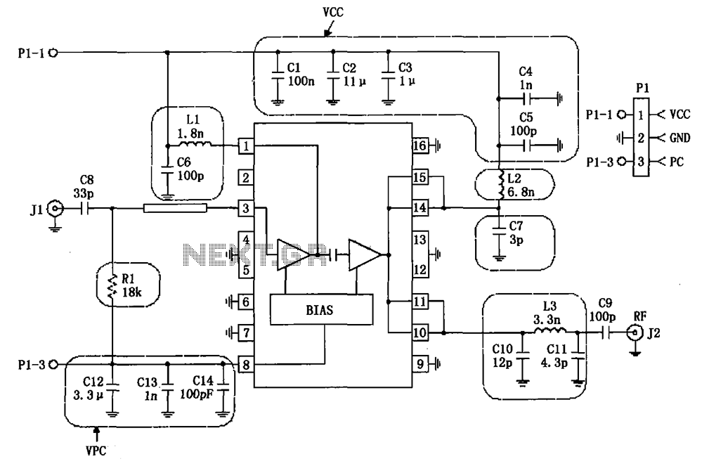
The RF2132 linear power amplifier circuit is depicted in the provided figure. A radio frequency (RF) signal enters through input pin 3 and is processed via a preamplifier. The final stage of the amplifier outputs a gain of 10....
The TDA8444 is a digital-to-analog (D/A) converter integrated circuit (IC) produced by Philips. It is designed to convert digital signals into analog signals. The TDA8444 IC utilizes a 16-pin dual in-line package, with specific pin functions and data outlined...
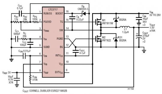
The LTC3717 is a synchronous step-down switching regulator controller designed for double data rate (DDR) and Quad Data Rate (QDR) memory termination. It utilizes a valley current control architecture to achieve very low duty cycles without the need for...