
SensorCircuit Of Automatic Room Lights Based On The CD4017 IC
The automatic room light circuit utilizes the CD4017 decade counter IC, which is designed to count pulses and drive multiple outputs. In this application, it functions as a control mechanism for the lights based on ambient light levels detected by the LDRs. The LDRs are positioned strategically to detect changes in light intensity; when the ambient light falls below a certain threshold, the resistance of the LDRs increases, triggering the circuit to activate the lights.
The circuit typically includes a comparator, which can be implemented using an operational amplifier (op-amp) or a simple transistor-based design. The output from the LDRs is fed into the comparator, which compares the voltage level against a reference voltage. When the voltage from the LDRs drops below the reference level, the comparator output changes state, signaling the CD4017 to activate the connected lighting load.
In addition to the basic components, the circuit may include a relay or a transistor to handle the higher current required by the lights, ensuring safe operation without damaging the sensitive IC. The circuit can also be equipped with adjustable resistors to fine-tune the sensitivity of the LDRs, allowing for customization based on the specific lighting conditions of the environment.
Overall, this automatic room light circuit provides an efficient solution for lighting control, enhancing convenience and energy savings by ensuring that lights are only activated in response to the presence or absence of natural light.The following circuit shows about Sensor Circuit Diagram Of Automatic Room Lights. This circuit based on the CD4017 IC. . Features: uses two LDRs, .. 🔗 External reference
Related Circuits
The brightness of a fluorescent light bulb or neon tube is not as easily adjustable as that of an incandescent bulb because it requires a much higher voltage to start. Once initiated, it operates at the electrical network voltage....
The battery charger circuit is designed to charge 6V 4.5 AH lead-acid batteries. The schematic is straightforward and utilizes only a few components. The IC LM317T serves as the core component of the circuit. It features an automatic charging...
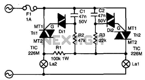
The circuit presented here ensures that if bulb La1 fails, bulb La2 will take over its function. In series with La1 is triac Tri2. Resistor R3 and capacitor C2 form a delay network. When the voltage across C2 exceeds...
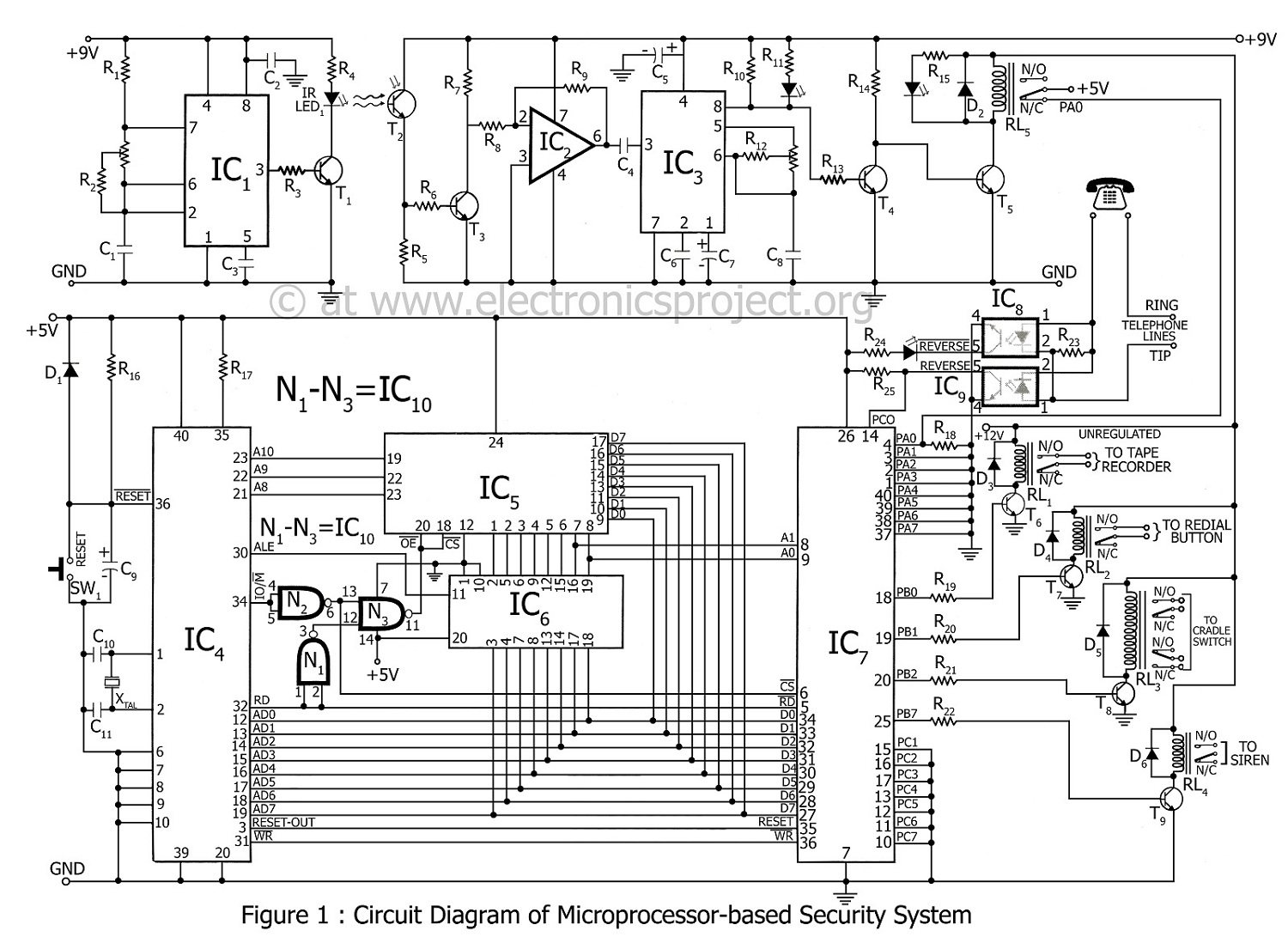
A microprocessor-based home security system project. This advanced security system not only notifies the user but also alerts the police immediately. In the 8085 microprocessor-based home security system, control is exercised over a siren, telephone (via cradle and redial...
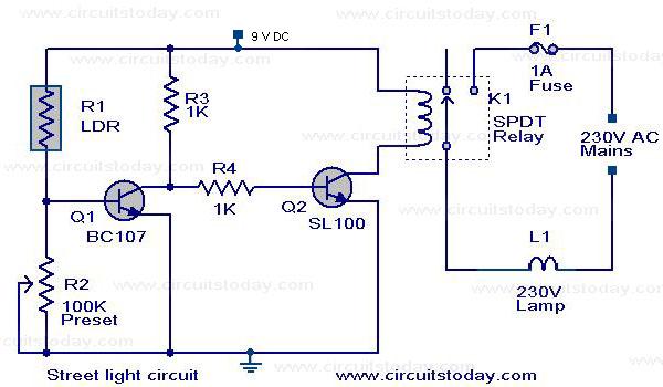
The circuit diagram of an Automatic Street Light Controller Circuit is explained in this post. The Automatic Street Light Controller Circuit is designed to automatically turn on street lights at dusk and turn them off at dawn. This functionality is...
A simple crystal oscillator can be constructed using a comparator from the LT1720/LT1721 series; however, this design may encounter several inherent limitations and issues. While the LT1720/LT1721 provides the correct logic output when one input falls outside the common...