
Factory secondary low-voltage distribution electrical panel wiring diagram
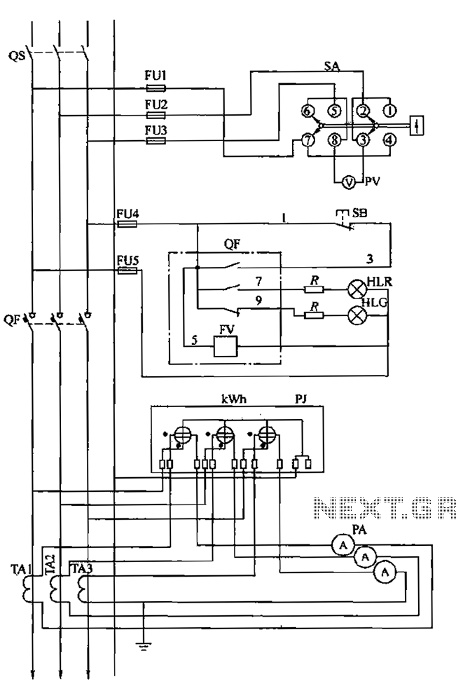
The BSL low-voltage distribution panel wiring diagram represents a critical system for ensuring reliable electrical distribution and safety. The voltage measuring circuit is essential for real-time monitoring of the three-phase power supply, which is crucial for maintaining the operational integrity of connected loads. The inclusion of the voltage switch (SA) allows for manual intervention when necessary, while the voltmeter (PV) provides a visual indication of voltage levels.
The secondary protection circuit plays a vital role in safeguarding the electrical system. The normally open contacts serve as a mechanism for signaling the operational status of the circuit. The red indicator light (HLt) activates when the circuit is closed, indicating normal operation, while the green light (HLG) signals when the circuit is open. The limiting resistor (R) is included to prevent excessive current from damaging the circuit components. This protection mechanism is crucial for preventing overloads, which could result in equipment failure or hazardous conditions.
In the event of an overload or voltage loss, the release coil (FV) is energized, triggering the load switch (QF) to disconnect the circuit. This automatic disconnection is a crucial safety feature that protects both the electrical equipment and personnel from potential hazards associated with electrical faults.
The energy metering loop circuit is designed to accurately measure the energy consumption of the system. The three-phase active energy meter (PJ) works in conjunction with the current transformers (TA1-TA3) to provide precise measurements of current flow. The current meters (PA) further enhance monitoring capabilities, allowing for real-time assessment of energy consumption. This data is essential for energy management and optimizing the efficiency of the electrical system.
Overall, the BSL wiring diagram illustrates a comprehensive approach to low-voltage distribution, integrating monitoring, protection, and metering functionalities to ensure safe and efficient operation of electrical systems. BSL is shown in low-voltage distribution panel wiring diagram. It consists of three parts, namely, the voltage measuring circuit, secondary circuit protection and energy meteri ng circuit. (1) using the voltage measuring circuit voltage switch SA and a voltmeter PV. Any time to monitor whether the three-phase power supply is operating smoothly, to meet the requirements required by the load voltage. (2) secondary protection circuit normally open contact, closing instruction signal red HLt, opening indication signal the green light HLG, limiting resistor R and the like.
By closing the line, opening the correct signal deaf culture, clear circuit status. Electrical equipment and wiring during operation, the time is now overload or loss of voltage, the voltage loss through the release coil energized Yan release FV and load switch QF constituted promptly cut off the line, ensure security lines, equipment and personal safety base. (3) energy metering loop circuit includes a three-phase energy metering active energy meter PJ and three current transformers TA1-TA3 and three current meter PA.
Use energy consumption metering system attack case, the current transformer and ammeter constitute a current measuring circuit, with l put line monitoring circuit current is normal or not,
Related Circuits
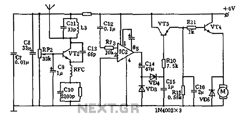
The homemade wireless remote control circuit diagram illustrates a motor remote control transmitter circuit. The circuit utilizes a 555 timer along with resistors R1, R2, RP1, diodes VD1, VD2, and capacitor C1 to create a variable duty cycle astable...
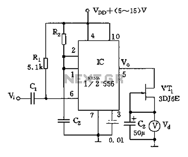
The circuit utilizes switch contacts that are proportional to the speed pulse signal Vi. A differential signal is fed into the trigger side of an integrated circuit (IC), specifically a 555 timer configured in monostable mode (1/2 556), to...
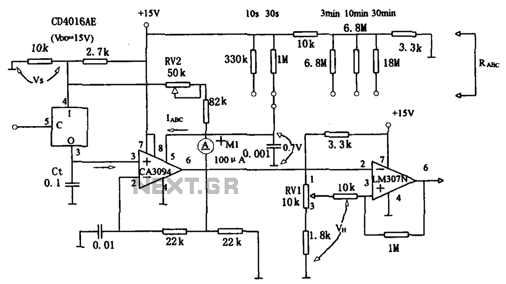
The long timer circuit utilizes an operational amplifier, specifically the CA3094, to control the discharge formula for extended timing. This is typically achieved by adjusting the variable resistor RV1, which alters the timing duration to meet specific requirements. The long...
Mercury, Oldsmobile, Plymouth, Pontiac, muscle cars, and antique classic car wiring diagrams are continuously being added to this site. The wiring diagram for the Porsche 911L engine from the 1968 model has undergone changes since the original scheme. For...
The part of the 2000 Chevrolet Chevy Blazer wiring diagram includes a power distribution schematic, fuel pump relay control, fuel pump and sender, splice pack, fuel pump prime connector, ground distribution schematic, underhood fuse block, and vehicle control module. The...
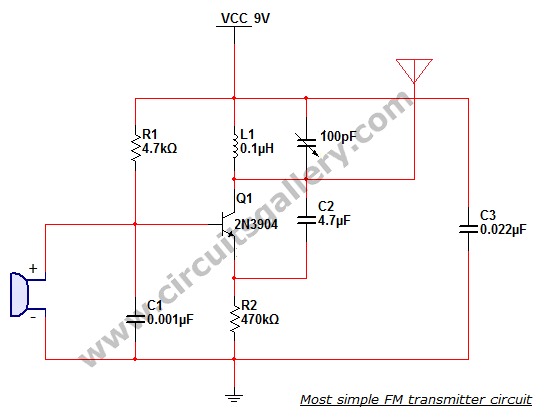
This is the simplest single transistor FM wireless transmitter circuit ever posted in CircuitsGallery. In the field of telecommunications, frequency modulation (FM) transmits information by altering the frequency of a carrier wave based on the message signal. FM utilizes...