
Fan speed controller using LM2941
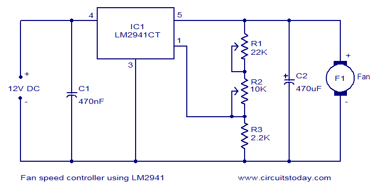
The 12V DC fan speed controller circuit employs the LM2941CT voltage regulator, which is notable for its low dropout voltage, enabling it to maintain a stable output voltage even with minimal input voltage overhead. This characteristic is particularly advantageous in battery-operated applications where efficiency is critical. The IC's built-in protections, including reverse polarity, thermal shutdown, and short-circuit protection, enhance the reliability and safety of the circuit, making it suitable for various applications where fan operation needs to be controlled under varying load conditions.
The circuit's configuration allows for easy adjustment of the fan speed through the use of potentiometers. The adjustment current (Iadj) is crucial for regulating the output voltage, which directly influences the fan's operational speed. By modifying the resistance of potentiometer R2, the user can fine-tune the output voltage. This design aspect provides flexibility, allowing the user to achieve the desired airflow based on specific cooling requirements.
In practical implementation, the circuit should be laid out on a suitable PCB to minimize parasitic inductance and resistance, ensuring stable operation. Proper heat dissipation measures must be considered, especially since the LM2941CT can supply up to 1A of current. Adequate thermal management will prevent overheating and extend the lifespan of the circuit components. Additionally, the choice of the fan should align with the circuit's specifications to ensure compatibility and optimal performance.Many electronic circuits related to fan speed controlling have been published here and this one is just another approach. The circuit diagram shown here is of 12V DC fan speed controller using the IC LM2941CT which is a low drop out 1A voltage regulator.
The IC has a dropout voltage as low as 0. 5 and has also many useful features like power supply reverse protection, thermal protection, short circuit protection etc. The maximum output current the IC can source is 1A. The 12V DC supply is connected between the Vin (pin4) and ground (pin3) of the IC. The load, which is the fan, is connected across the Vout (pin5) and ground (pin3) of the IC. The network comprising of potentiometers R1, R2 and resistor determines adjust current (Iadj) of the IC. By varying the Iadj using the POT R2 we can adjust the output voltage of the IC and hence the fan speed.
🔗 External reference
Related Circuits
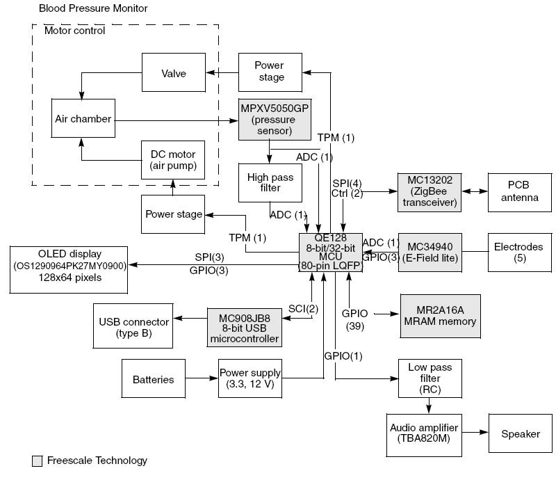
This article demonstrates the implementation of a system capable of measuring arterial blood pressure values. The arterial blood pressure measurement system typically consists of several key components, including sensors, signal processing units, and display interfaces. The primary sensor used in...
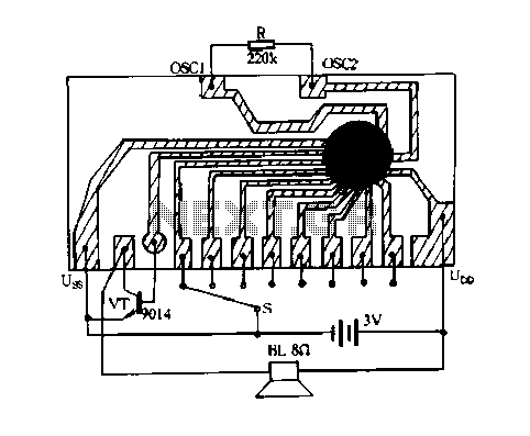
Constantly changing light and sound analog controller circuit 05 The circuit described is an analog controller designed to modulate light and sound in a dynamic manner. This type of circuit typically employs a combination of resistors, capacitors, and operational amplifiers...
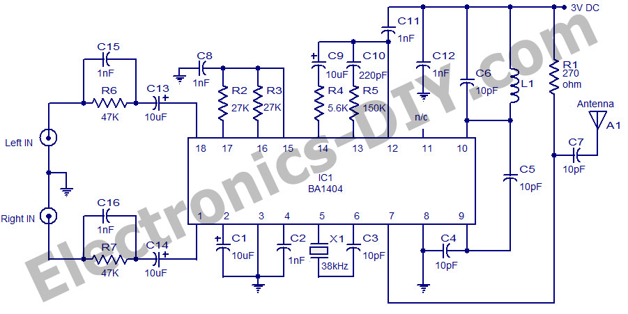
A high-quality stereo FM transmitter circuit is presented here. The circuit utilizes the IC BA1404 from ROHM Semiconductors. The BA1404 is a monolithic FM stereo modulator that incorporates a built-in stereo modulator, FM modulator, and RF amplifier circuitry. The...
Fire alarm circuit using an LDR (Light Dependent Resistor) as a flame sensor. It warns the user about fire accidents by detecting smoke produced during a fire. As smoke passes between an LED and an LDR, the amount of...
A robot can be defined as an electro-mechanical system with the capability of sensing its environment, manipulating it, and acting according to a preprogrammed sequence. It is a machine that... Robots are complex systems that integrate various components to perform tasks...
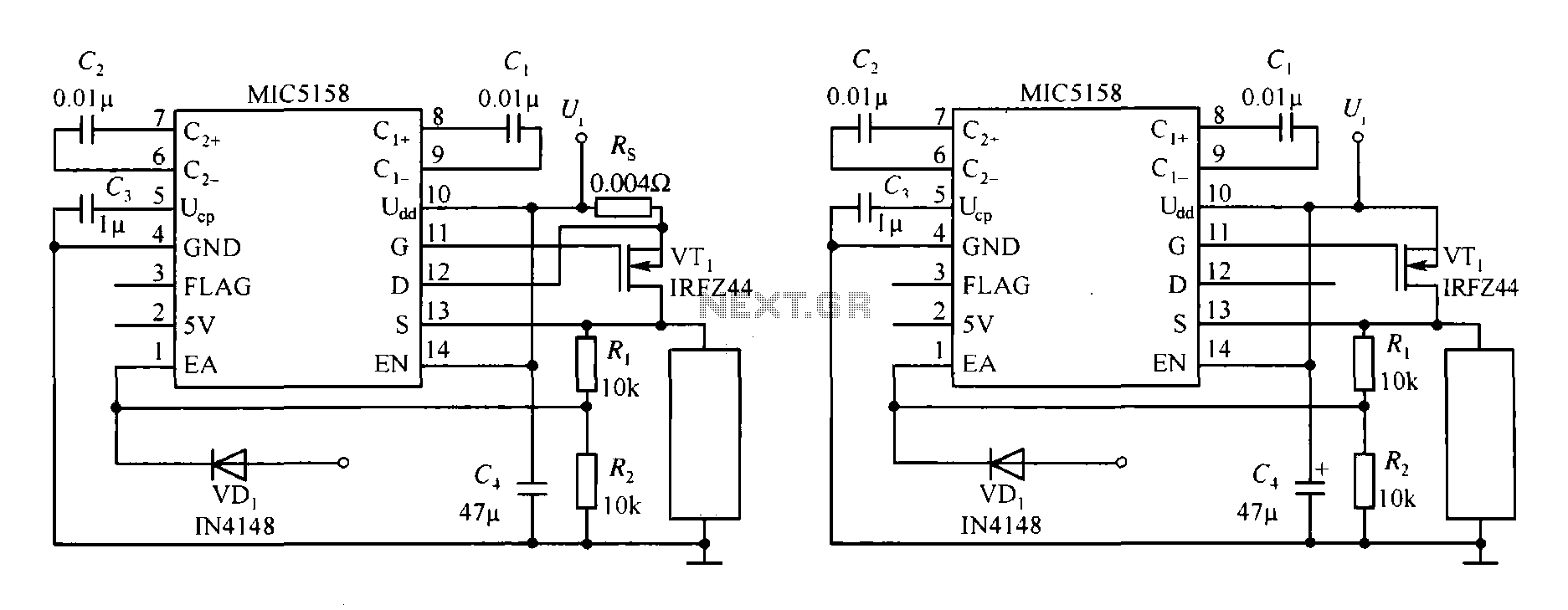
The MIC5158 is part of a high-speed switching circuit diagram that focuses on the rising edge. The MIC5158 is a precision voltage reference and high-speed switching device that is commonly utilized in various electronic applications requiring rapid signal transitions. In...
Warning: include(partials/cookie-banner.php): Failed to open stream: Permission denied in /var/www/html/nextgr/view-circuit.php on line 713
Warning: include(): Failed opening 'partials/cookie-banner.php' for inclusion (include_path='.:/usr/share/php') in /var/www/html/nextgr/view-circuit.php on line 713