
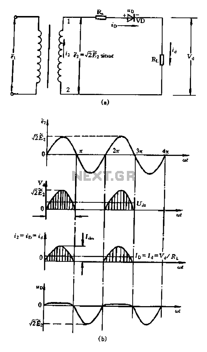
Fast half-wave rectifier

A precision half-wave rectifier circuit is designed to convert an AC signal into a unidirectional output while maintaining high accuracy in the rectification process. This is achieved through the use of an operational amplifier (op-amp), which enhances the performance of traditional rectifiers by minimizing voltage drops and improving linearity.
In this configuration, the op-amp is employed to amplify the input AC signal during the positive half-cycle while effectively blocking the negative half-cycle. The circuit typically consists of the op-amp, a diode, and resistors that set the gain and establish the feedback loop. The diode is placed in the feedback path of the op-amp, allowing current to flow only during the positive half of the input waveform.
The precision of the rectifier is largely attributed to the characteristics of the op-amp, which can provide a gain that compensates for the forward voltage drop of the diode. This results in an output that closely follows the input signal for the positive half-cycles, achieving the stated rectification accuracy of 1% over a frequency range from DC to 100 kHz.
To ensure optimal performance, careful selection of the op-amp is crucial, as parameters such as bandwidth, slew rate, and input offset voltage can significantly impact the rectification accuracy. Additionally, the circuit layout should minimize parasitic capacitances and inductances to maintain fidelity at higher frequencies.
Overall, this precision half-wave rectifier design is particularly useful in applications requiring accurate signal processing, such as in measurement systems, signal conditioning, and data acquisition, where precise representation of the input signal is essential.Precision half wave rectifier using an operational amplifier will have a rectification accuracy of 1% from dc to 100 kHz.
Related Circuits
A bridge rectifier capacitor filter serves as a primary power supply for current amplifier circuits. This power supply configuration is straightforward and offers enhanced performance. The bridge rectifier circuit is a full-wave rectifying circuit, meaning it converts both the...

This circuit performs a rapid battery test without requiring a power supply or costly moving-coil voltmeters. It features two ranges: when SW1 is configured as depicted in the circuit diagram, the device can test batteries ranging from 3V to...
This circuit is an RMS-calibrated AC voltmeter that provides average readings. Removing capacitor C2 eliminates the averaging function, resulting in a precision full-wave rectifier, while removing capacitor C1 transforms the circuit into an absolute value generator. The operation of...
PWM rectifier power controller power supply. Visit the page to read the explanation about the associated circuit diagram. A PWM (Pulse Width Modulation) rectifier power controller is a sophisticated electronic circuit designed to convert alternating current (AC) to direct current...
This simple battery charger circuit is designed for NiMH/NiCd batteries. It requires no microcontroller or any programming. Linear Technology Corporation. The described battery charger circuit is intended for use with nickel-metal hydride (NiMH) and nickel-cadmium (NiCd) batteries, which are commonly...
When the current through the load exceeds a level determined by the position of the wiper on the 1k wire-wound pot, this circuit cuts off the load immediately. If S1 is open, the range is approximately 300-650 mA, and...