
fcd fuel cut defencer

The FCD circuit design incorporates essential components such as resistors, capacitors, and an operational amplifier to achieve the desired clamping behavior. The active clamp configuration allows for dynamic adjustment of the output signal based on the input boost pressure. The operational amplifier is configured in a non-inverting mode to ensure that the output closely tracks the input until the clamping threshold is reached.
The circuit may include a voltage reference source to set the clamping voltage accurately. This voltage reference can be derived from a Zener diode or a precision voltage reference IC that ensures stable operation across varying temperatures and supply voltages.
The feedback loop within the operational amplifier configuration is crucial for maintaining the desired output characteristics. The choice of resistor values in the feedback path directly influences the response time and accuracy of the clamping action.
Furthermore, the layout of the circuit should minimize noise and interference, particularly in automotive environments where electromagnetic interference is prevalent. Shielding and careful routing of signal traces can enhance the reliability of the FCD circuit.
In conclusion, the FCD circuit serves as a critical component for managing boost pressure in performance applications, providing a safeguard against fuel cut-off while maintaining engine performance. Proper implementation and understanding of the circuit's operation are essential for ensuring safe and efficient engine operation under increased boost conditions.This article presents a simple FCD circuit that can be built by anyone with moderate electronics assembly expertise. In addition, the article covers the reasons why an FCD is needed, why this FCD is superior to other FCD designs, and the theory of operation.
By the time you are done reading this article, you will hopefully understand a little more about how your TII works, and a little electronics as well. The FCD (acronym for Fuel Cut Defencer) is any device that prevents the stock ECU from cutting fuel to the rear rotor when the boost exceeds a preset boost level. This maximum safe boost level and behavior is coded into the firm ware in the engine management unit and can not be changed without reprogramming the ECU.
The maximum allowed boost pressure is about 8. 6 psi. The way an FCD defeats the fuel cut is by lying to the ECU about what the boost pressure is. The FCD is placed betw1een the boost sensor and the ECU where it modifies the boost pressure signal by some amount so that as the boost pressure rises above the preset "safe limit", the ECU continues to see a signal that is below the limit. There are a couple of immediate consequences to this fooling around. As the boost rises, the ECU must increase the amount of fuel being delivered to the engine in order to maintain safe and efficient operation.
As the FCD starts lying to the ECU, the ECU will begin to under-compensate for the rise in pressure leading to a gradual leaning of the air-fuel mixture. The amount of error increases as the boost rises. For relatively small errors, the only penalty is efficiency. As the error gets larger, however, detonation becomes likely, exacerbated by the high boost pressures and accompanying high intake charge temperatures.
Detonation under these conditions will quickly kill an engine. So, before we go any further, be forewarned that using an FCD and increasing boost pressure without also compensating for the ECU error with fuel enrichment (and preferably more efficient intercooling) can cause serious damage to your engine! What you would like to have is an FCD that leaves the boost signal alone until it approaches the cutoff level, and then kicks in, holding the signal below the critical level.
This can be accomplished with a circuit element called a clamp. The FCD circuit described in this article utilizes an active clamp which performs the necessary function very efficiently. As you can see from the graph, FCD #1 is a clamp circuit. The output follows the input until the clamp voltage of 3. 33 V (about 6 psi) is reached. At this point the output stops rising. FCD #2 works by reducing the input by a percentage. This creates an error across the entire range, as opposed to only when the boost is over the limit. (At a safe 5. 5 psi, the computer is only seeing 4 psi. ) This is not the desired behavior. Our FCD works similarly to FCD #1, except we have raised the clamping voltage to 3. 65V (about 7. 9 psi). NOTE: If you look closely at the graph, you can see that our FCD has an output that is 0. 05 V below the input up to the clamping voltage. I have since fixed this problem by changing R1 from 2. 2k ohms to 680 ohms. The FCD output is now within 0. 02V of the input, right up to the clamping voltage. Sorry, I didn`t have time to rerun the numbers. The measurements above were obtained with the FCD under test connected to the TII boost sensor and TII wiring harness in order to simulate actual operating conditions as closely as possible.
Pressures were read on a diagnostic pressure/vacuum gauge. If you are interested in it, I would be happy to send you the Excel spreadsheet containing 🔗 External reference
Related Circuits
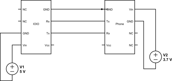
This project utilizes Sparkfun's IOIO for Android, focusing on power consumption concerns. The IOIO board can provide the phone with 500 mA charging, which may be excessive for continuous operation. The proposed solution is to power both the phone...
The project involves the development of a miniature transmitter suitable for implantation in a rat's body, capable of transmitting 416-bit data samples at a rate of 400 samples per second. It is designed to have a detection range of...
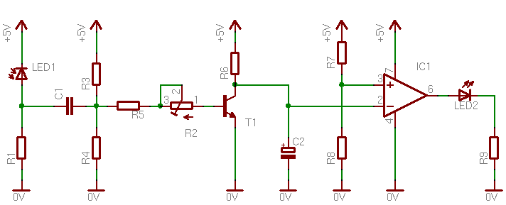
A circuit designed to detect the interruption of a light beam. The initial circuit was a light/dark detector using a photoresistor, which, while capable of detecting light interruptions, suffered from significant interference due to ambient light. This led to...

Voltage variations and power cuts adversely affect various equipment such as TVs, VCRs, music systems, and refrigerators. This simple circuit will protect costly equipment from high and low voltages and voltage surges when power resumes. It also produces a...
This circuit illustrates a Lie Detector Circuit Diagram. It is based on the principle that a person's skin resistance varies when they experience emotional stress. The Lie Detector Circuit operates on the principle of galvanic skin response (GSR), which measures...
A 1984 F-350 crew cab with a 460 engine has a malfunctioning fuel gauge and is unable to pump fuel from the front tank. The initial troubleshooting steps included replacing the switch in the dashboard and the switch on...