
Fet Audio Mixer electronic circuit

The circuit employs operational amplifiers (op-amps) configured in a summing amplifier arrangement to achieve the mixing functionality. Each input channel is connected to a resistor that feeds into the inverting terminal of the op-amp. The resistors are selected to ensure that the levels of the incoming signals are appropriately balanced, preventing any single channel from dominating the output.
The output of the op-amp provides the mixed audio signal, which can then be sent to a speaker or further processed in an audio system. Power supply requirements for this circuit are minimal, typically requiring only a dual power supply (positive and negative) to operate the op-amps effectively.
By adding additional input channels, one can easily increase the number of audio sources mixed together. Care should be taken to maintain consistent resistor values across all channels to ensure uniform mixing and avoid distortion in the final output. Additionally, bypass capacitors may be included near the power supply pins of the op-amps to filter out any noise and ensure stable operation.
This circuit is particularly useful in applications such as audio processing, sound reinforcement systems, and various consumer electronics where multiple audio sources need to be combined efficiently. Overall, the design is straightforward, cost-effective, and versatile for a range of audio mixing applications.This simple circuit mixes two or more channels into one channel (eg. stereo into mono). The circuit can mix as many or as few channels as you like and consumes very little power. The mixer is shown with two inputs, but you can add as many as you want by just duplicating the sections which are clearly visible on the schematic. 🔗 External reference
Related Circuits
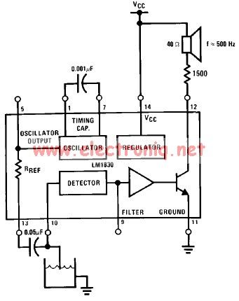
The LM1830 low-level detector can utilize an audio indication (speaker) or a visual indicator (LED - light-emitting diode) that activates when the level is too low. This low-level detector circuit generates a 500 Hz audio signal when the level...
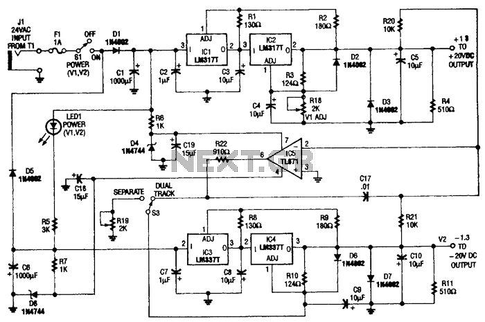
This circuit is useful for a bench supply in the lab. Separate or tracking operation is possible. The regulators should be properly heatsinked. Tl is a 24-Vac wall transformer of suitable current capacity. The described circuit functions as a laboratory...
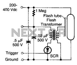
This circuit is beneficial for applications requiring a low-energy flashing alarm. A DC supply ranging from 200 to 400 volts should possess sufficient internal resistance to charge a 0.5 microfarad capacitor between flashes. This charging process should take approximately...
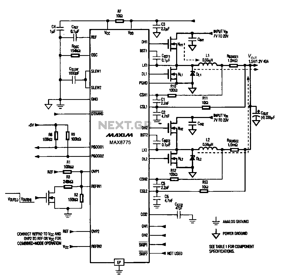
Notebook computer chip power supply circuit, which generates the PWM circuit using MAX8775. The notebook computer chip power supply circuit utilizes the MAX8775 integrated circuit to generate a Pulse Width Modulation (PWM) signal. The MAX8775 is a high-efficiency step-down voltage...
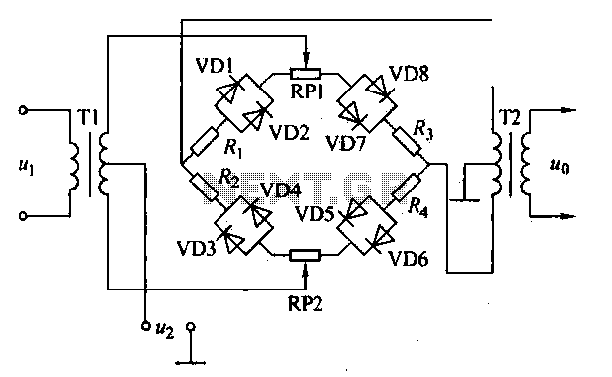
An AM diode ring circuit consists of four diodes arranged in a ring configuration, commonly referred to as a diode ring modulator circuit. This circuit offers significant advantages due to the characteristics of the diodes and the use of...
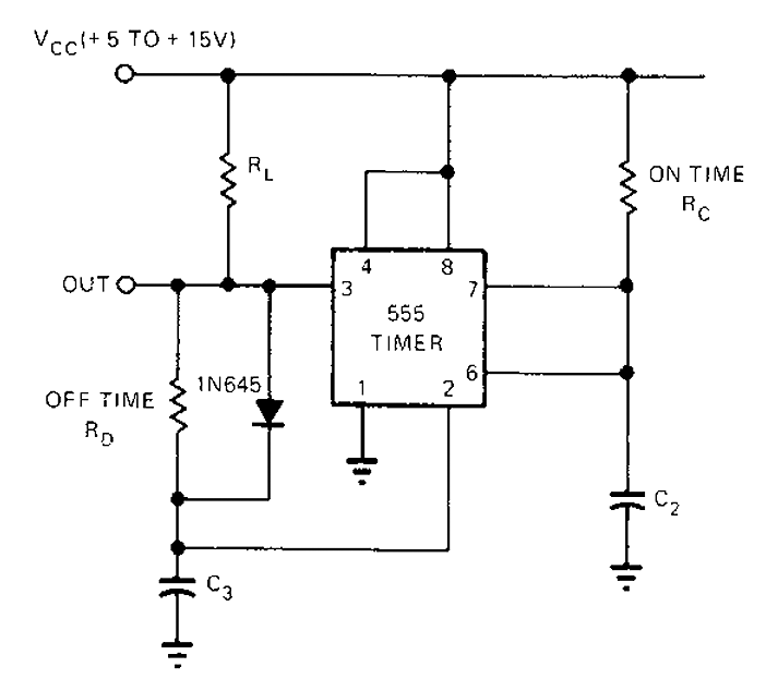
The 555 timer circuit has unsteady open and closing times that are independent of one another. One time constant is given by 1.1RcC2, while another time constant is defined as 1.1RcC3. The free-running period is the sum of these...