
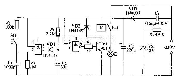
Flash Signal Alarm Circuit
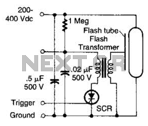
The circuit operates by utilizing a capacitor that stores energy and subsequently discharges it to produce a flashing signal. The time constant (τ) is defined as the product of the resistance (R) and capacitance (C), τ = R × C. For this application, with a capacitance of 0.5 µF, the time constant will dictate how quickly the capacitor charges and discharges, thus controlling the flashing frequency of the alarm.
To achieve the desired performance, the selected resistor should be in the range specified, ensuring that the capacitor charges adequately before discharging. For example, using a resistor of 500 kΩ will yield a time constant of approximately 0.25 seconds (τ = 500,000 Ω × 0.5 × 10^-6 F), allowing a flashing rate of about 1 second. For applications requiring faster flashing rates, a lower resistance value can be incorporated, which will decrease the time constant and increase the frequency of the flashing signal.
The circuit should also include a suitable switching mechanism, such as a transistor or a relay, to control the discharge of the capacitor. This switching device can be activated by the voltage across the capacitor, ensuring that the alarm flashes only when sufficient charge is present. Additionally, it is advisable to incorporate a diode in parallel with the capacitor to prevent reverse current flow, which could damage the circuit components.
Overall, this low-energy flashing alarm circuit is effective for various applications, including security systems and notification devices, where low power consumption is crucial. Proper selection of components will ensure reliable operation and desired flashing rates tailored to specific requirements. This circuit is useful if you need a low-energy flashing alarm. The 200 to 400-dc supply should have enough internal resistance to charge the 0.5 capacitor between flashes, about 2 or 3 time constants, which means about 500 kQ to 1 for a 1-s rate. Use lower values for higher rates. 🔗 External reference
Related Circuits
This infrared transmitter utilizes pulse width modulation (PWM). The transmitter is equipped with an LM567 tone decoder circuit. An audio signal (at least 50 mV peak-to-peak) is amplified with transistor T1 and subsequently used to modulate IC1. The frequency...
This circuit is a modification of a high and low voltage cut-off with delay and alarm circuit that was featured in Circuits Today. It has been tested and found to be reliable. The circuit can be adapted with minor...
Light flashing circuit. This circuit is designed to create a small lamp that flashes with a signal at a rate of one flash per second, controlled by adjusting the lamp voltage through resistor R1. The rate is adjustable to...
A 2-input NAND gate integrated circuit is used in the fabrication of a digital delay lamp circuit. This circuit is energized by a simple capacitive voltage rectifier, which operates by crossing the half line. The output terminal indicates the...

These circuits could be used as the basis for Model Railroad DCC Boosters or PWM motor controllers. The first schematic is for a basic 3 Amp - DCC Booster using the LMD 18200 CMOS, H-Bridge. Included in the design...
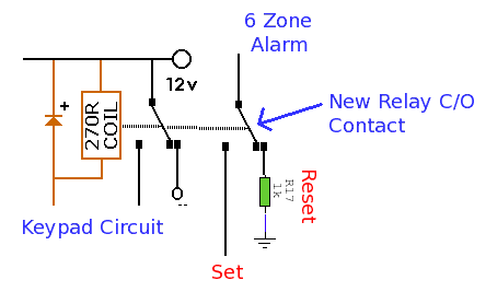
This alarm system features six independent zones, one timed entry/exit zone, a seven-segment LED display, and a test or walkthrough capability. It is designed for use in small office or home environments and can be adapted to utilize a...