
FET Colpitts Oscillator (Microwave)
")
The construction of a 430 MHz transmitter for microwave applications involves several critical components and considerations to ensure proper functionality. The design typically includes an oscillator circuit, which generates the desired frequency, and a power amplifier to boost the signal for transmission.
Key components in the circuit may include a crystal oscillator or a phase-locked loop (PLL) to establish the 430 MHz frequency. The oscillator's output must be stable and precise, as any deviation can affect the performance of the transmitter. A low-pass filter may also be incorporated to eliminate unwanted harmonics and ensure that only the desired frequency is transmitted.
The power amplifier should be selected based on the required output power and efficiency. It is essential to ensure that the amplifier operates within its specified frequency range and that it is properly matched to the load to avoid reflections that could damage the circuit.
Additionally, the layout of the circuit board is crucial. It should minimize parasitic capacitances and inductances, which can lead to signal degradation. Proper grounding techniques and the use of bypass capacitors can help maintain signal integrity.
Testing the circuit requires the use of an oscilloscope or a frequency counter to measure the output frequency. If no output is observed, potential issues may include incorrect component values, poor connections, or insufficient power supply levels. Thorough troubleshooting is necessary to identify and rectify these problems to achieve a functional microwave transmitter.Hi there. I`ve building a 430Mhz Transmitter for microwave. And for some strange reason i couldn`t get any output frequency from my circuit. I`ve.. 🔗 External reference
Related Circuits
Can be directly connected to CD players, tuners and tape recorders. Simply add a 10K Log potentiometer (dual gang for stereo) and a switch to cope with the various sources you need. A correct grounding is very important to...
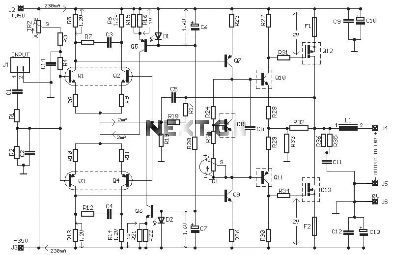
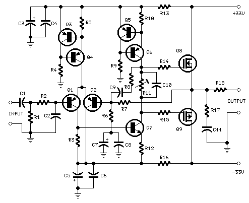
This HEXFET Audio Amplifier 65 Watts circuit diagram includes three circuit images. For a more comprehensive understanding, refer to the original post titled "HEXFET Audio Amp 65 Watts." The post not only provides circuit information but also includes a...
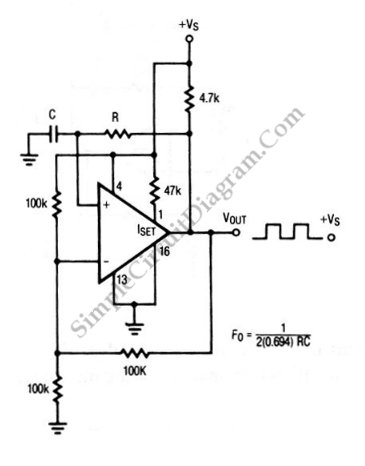
The circuit depicted in this schematic diagram is a square-wave oscillator circuit. The primary component of this oscillator circuit is the LP165/365 comparator. The square-wave oscillator circuit utilizes the LP165/365 comparator to generate a continuous square wave output. The...

This is a circuit known as a Wien bridge oscillator. The circuit features both positive and negative feedback loops and operates under the control of an operational amplifier (op-amp). The oscillation frequency is determined by the RC time constant,...
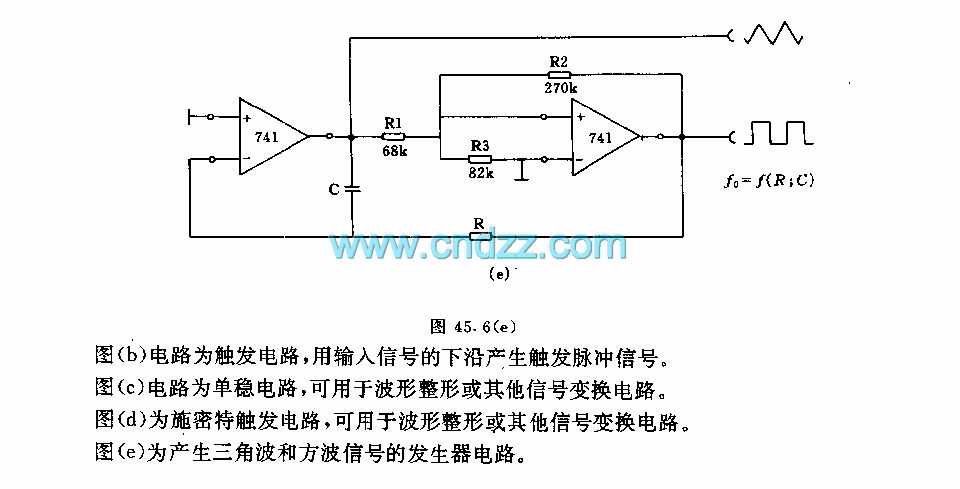
Figure a illustrates a multivibrator circuit capable of generating a square wave signal. Figure b depicts a flip-flop circuit that utilizes the falling edge of the input signal to produce a trigger pulse signal. Figure c represents a monostable...
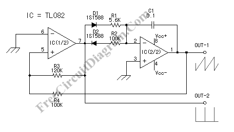
A sawtooth wave oscillator is utilized in cathode ray tube deflection circuitry, in a PWM modulator, or in analog to digital conversion applications. The sawtooth wave oscillator generates a waveform that linearly rises and then sharply drops, resembling the...