
Sawtooth Wave Oscillator

The sawtooth wave oscillator generates a waveform that linearly rises and then sharply drops, resembling the teeth of a saw. This waveform is particularly useful in various electronic applications, such as in cathode ray tubes (CRTs) where it serves to control the horizontal and vertical deflection of the electron beam, allowing for the display of images on a screen. In pulse-width modulation (PWM) circuits, the sawtooth waveform can be compared with a reference signal to produce variable duty cycles, which are essential for controlling power delivery to loads in applications such as motor control and lighting dimming.
In analog to digital conversion, the sawtooth waveform can be employed in the sampling process, where it provides a consistent timing reference for capturing the analog input signal at regular intervals. This ensures that the digitization process occurs accurately and consistently.
The circuit design for a sawtooth wave oscillator typically involves a capacitor and a resistor in conjunction with a comparator or an operational amplifier. The capacitor charges linearly through the resistor, and once it reaches a predetermined voltage threshold, the comparator resets the capacitor, producing the characteristic sawtooth waveform. Additional components, such as diodes and transistors, may be included to enhance the performance and stability of the oscillator, ensuring that the output waveform maintains its shape and frequency consistency under varying load conditions.
Overall, the sawtooth wave oscillator is a versatile component in electronic systems, serving critical functions across a range of applications.Sawtooth wave oscillator is used in cathode ray tube deflection circuitry, in a PWM modulator, or in a analog to digital conversion. You can also use it in your. 🔗 External reference
Related Circuits
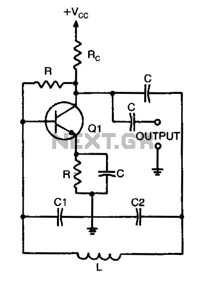
When calculating the resonant frequency, use the formula C1C2/(C1+C2) for the total capacitance of the L-C circuit. In an L-C (inductor-capacitor) circuit, the resonant frequency is a critical parameter that determines the frequency at which the circuit will oscillate. The...
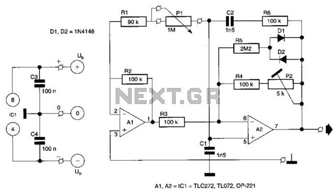
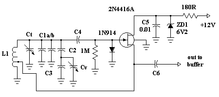
This circuit is a sine wave oscillator with a frequency range from 5 Hz to 5 kHz. The capacitors C1, C2, and C3, with a combined value of 100 pF, produce a frequency of 5 kHz. To achieve different...
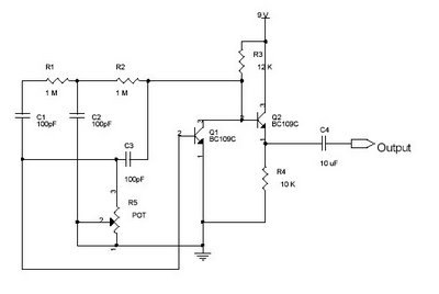
This circuit utilizes a single potentiometer to control a frequency range from 300 Hz to 3000 Hz. A FET operational amplifier is employed at stages A1 and A2. The upper frequency limit is dictated by the gain-bandwidth product of...
The schematic illustrates the division of a crystal oscillator signal by the crystal frequency to achieve a precise 1-second time base with an accuracy of 0.01%. Two cascaded 12-stage counters (CD4040) create a 24-stage binary counter, with specific bits...
Hartley oscillators are inductively coupled, variable frequency oscillators that can be series or shunt fed. They feature a center-tapped inductor and a tuning capacitor, which simplifies the circuit construction. The schematic includes a buffer stage and an amplifier stage...
A phase-shift audio oscillator exhibits excellent distortion characteristics due to "softened" diode limiting provided by the 1N914 diode and a resistor divider, along with degenerated gain facilitated by a 68-ohm emitter resistor. To minimize distortion, it is recommended to...