
Spitfire/GT6 Relay and Blinker Information
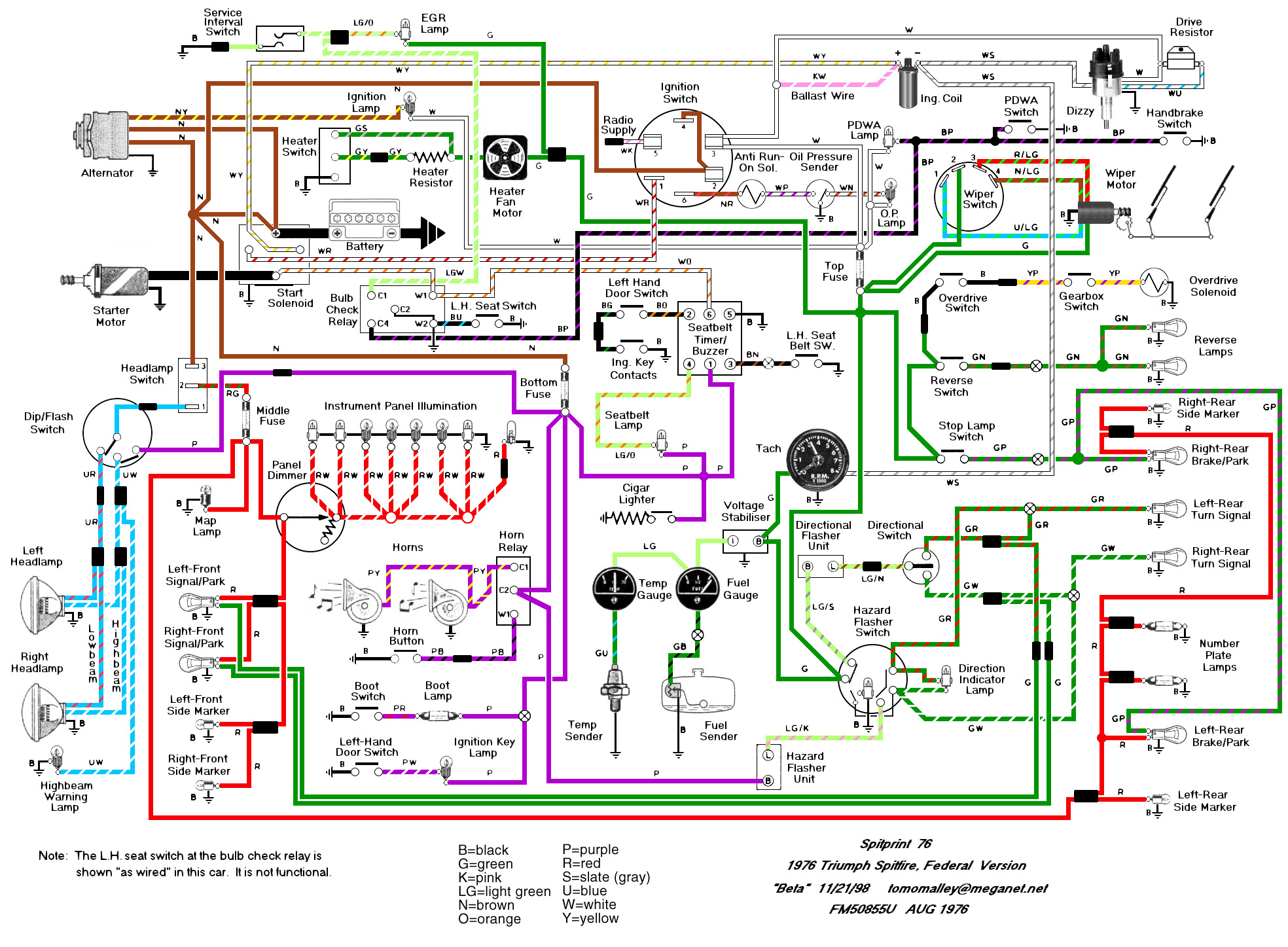
The Spitfire's relay configuration is critical for the proper functioning of various electrical components within the vehicle. The grouping of relays on the bulkhead near the master cylinders is designed to optimize space and accessibility, particularly for maintenance and troubleshooting. The Hazard Flasher relay plays a vital role in signaling the vehicle's presence during emergencies, while the Horn relay provides essential auditory warnings to other road users.
The relay designated as the "Pre-Driving Checks" relay is particularly notable due to its involvement in multiple safety systems. Its connections to the seatbelt warning light/buzzer ensure compliance with safety regulations, alerting the driver and passengers to fasten their seatbelts before driving. The EGR service light indicates the operational status of the exhaust gas recirculation system, which is crucial for reducing emissions and enhancing engine performance. The PDWA light serves as an important safety feature by warning the driver of potential brake system failures, thereby promoting safe driving practices.
The combination of the Hazard and Blinker relays in later models reflects an evolution in design aimed at simplifying the electrical system and reducing component count. The relocation of this combined relay behind the dashboard illustrates a shift towards a more integrated approach to vehicle wiring, enhancing aesthetics and potentially reducing the risk of damage from external elements.
For technicians and enthusiasts working on the Spitfire, understanding the accurate wiring configuration and relay designations is essential. The discrepancies in the Haynes manual highlight the importance of consulting multiple sources or verified wiring diagrams to ensure proper diagnosis and repair of electrical issues. Access to a reliable wiring diagram can facilitate effective troubleshooting and maintenance, ultimately contributing to the longevity and reliability of the Spitfire's electrical system.The Haynes manuals is extremely confusing regarding the labeling of the relays on Spitfires. The two ways they confuse readers is 1. the illustrations show right hand drive cars with different locations for relays, and 2. the naming of the relays is strange (at least to North American Spit owners). There are three relays grouped together on the bu lkhead next to the master cylinders (not the battery box as Haynes says. this is for Right Hand Drive cars in the UK). The relays are the Hazard Flasher relay, Horn relay, and another confusingly named relay: green/white (to the C1 terminal), black/purple (to the C4 terminal), white/orange (to the W1 terminal), Double black combo (black/blue & black to W2 with a black jumper between C2 and W2) This relay should be called "Pre-Driving Checks" relay. The Haynes manual shows it in the photo calling it the Overdrive relay. When researching this page I found it also called Bulb Check relay and Starter relay. Apparently its job is to have a hand in the control such US government mandated devises as the seatbelt warning light/buzzer, EGR service light, and the PDWA (brake failure) light.
Note that the Hazard and Blinker relays were combined into a single one for 1978-80 cars and was located behind the dash (somewhere below the tach or speedo). This "Flasher" relay now had 3 wires (light green/gray, light green/brown and green/light green). If you haven`t guessed, the Haynes manual`s wiring diagram is VERY wrong around this relay on 76 cars.
A great wiring diagram is available for download however. (1. 1Mb) 🔗 External reference
Related Circuits
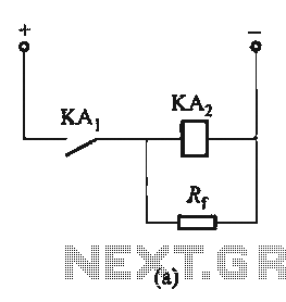
The circuit depicted in Figure 6-24 includes a relay coil with both ends connected in parallel to either a resistor Rf or an auxiliary diode VD. This configuration is equivalent to providing power after a short circuit, which increases...
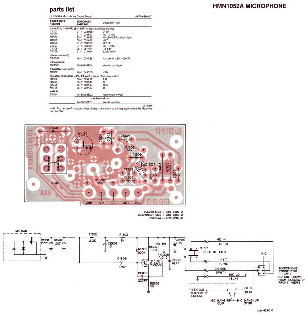
Regardless of the label on the radio or the claims made by the seller, no Spectra radio will function across the entire 136-174 MHz (high band) or 403-512 MHz (UHF) frequency range. Each unit operates within a specific portion...
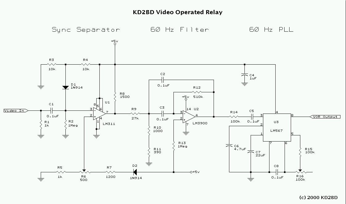
Many Video Operated Relay (VOR) circuits have been published in recent years for use in connection with ATV repeater controllers or automatic videotape logging systems. Unfortunately, many of these circuits fail to properly detect certain video signals depending on...
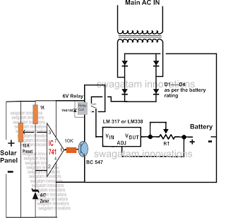
The automatic changeover relay circuit was requested by Mr. Karimulla Baig. The circuit is designed to charge a connected battery at a constant current using power from a solar panel. In the absence of solar energy, such as during...
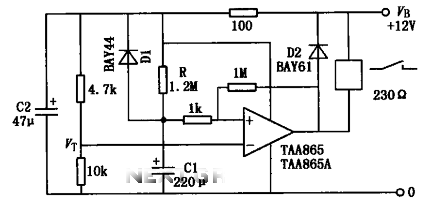
The circuit illustrated in the figure is a delayed release operational amplifier relay circuit. When the power switch is activated, a resistor of 4.7k is connected to the inverting input terminal of the operational amplifier. Additionally, a 10k resistor...

This circuit utilizes a Power Battery Terminal (PBT) to facilitate simple relay output and auxiliary power connections. An LED on each channel serves to indicate the status of the relay. Berg pins are provided for connecting power and trigger...