
how to make solar powered robot

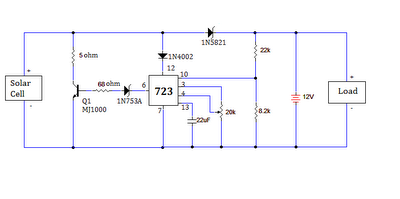
The circuit design for this project utilizes a solar panel as the primary energy source, which is crucial for powering the motor that drives the robot. The solar panel generates direct current (DC) when exposed to sunlight, which is then used to charge the capacitor. The capacitor acts as a storage device, allowing the energy collected during sunlight exposure to be utilized for robot movements when the solar panel is not actively generating power.
The 1381 component, a voltage comparator, plays a vital role in regulating the operation of the motor. Once the voltage across the capacitor reaches a predetermined threshold, the 1381 triggers, allowing current to flow to the motor. This mechanism ensures that the robot operates intermittently, creating a pattern of movement that can be adjusted by varying the capacitance and resistance values in the circuit.
The choice of capacitor value is particularly important as it directly influences the robot's behavior. Increasing the capacitance leads to longer activity bursts but also results in longer pauses between movements. Conversely, a smaller capacitor will produce shorter bursts of activity with more frequent intervals. This tunability allows for experimentation, enabling builders to customize the robot's performance based on their preferences.
The inclusion of a diode, although not necessary in this configuration, serves as a protective measure in other applications where a battery is involved. It prevents reverse current flow that could deplete the battery when the solar panel is not generating power. In this case, since the project operates solely on solar energy without a battery, the diode can be omitted, simplifying the circuit.
Overall, this project not only provides a practical introduction to basic electronic components and circuit assembly but also emphasizes the importance of experimentation and iterative learning in electronics. By engaging in this project, builders can gain valuable hands-on experience that will serve as a foundation for more complex electronic endeavors in the future.It is based on the Miller solar engine and has no digital electronics involved. But before we get started, it must be said that a robot is defined as "a mechanical intelligent agent which can perform tasks on its own". Note that the definition does not state that it has to be in a particular `form`! So, though the robot we are going to build will look crappy, it will work and delight your heart. This project is more of a `proof-of-concept` than the actual construction of an amazing robot! It we were to build an actual `human-looking` robot, the difficulty level would catapult manifold. With that being stated, here we go: `Moderately Challenging` - This DIY project involves building a basic circuit with a solar panel, capacitor, diode and transistor. The ability to make connections by reading a circuit diagram is absolutely essential though we try to simplify it in this tutorial.
It would help if the `builder` is familiar with the use of the soldering iron. Once you have gathered all the essential components of the right specifications, it would take less than half an hour to make the circuit and have the robot up and running! 8. The other terminal of the motor is connected to the 3300uf capacitor which is in turn connected to the other terminal of the solar panels.
(The diagram shows 4700uf. Don`t worry. As you will see later, the values can be altered to get different effects for the robot. ) Ans: This project will help you develop the confidence on many future electronic projects. Do not worry if you don`t get it right the first time. The connections are simple but they may get confusing for the first timer. So make atleast two or three attempts before giving up. If you make those attempts, you surely will not have to give up is our belief. Ans: The diode can actually be discarded. The diode is actually added to prevent the battery discharge through the solar panel. Since we are not using a battery and the circuit does not need the capacitor to retain charge when the panel is not in the light, the diode becomes superfluous. But as we said, this is based on the Miller solar engine and so the circuit diagram shows the diode. If you are using one, any diode will do. The specifications are not important. 2. Vary the resistor and capacitors to find the optimum solution for your robot. This will alter the power going to the motor ( and hence the intensity of the robot movements) and the time interval between the movements.
The solar energy is stored by charging the capacitor in circuit and when a threshold level is reached, the 1381 part gets triggered and works the motor. 4. The values of the small capacitor determine the `burst` of activities. Larger the values, longer will be the dance but intervals between will also be longer and vice versa.
🔗 External reference
Related Circuits
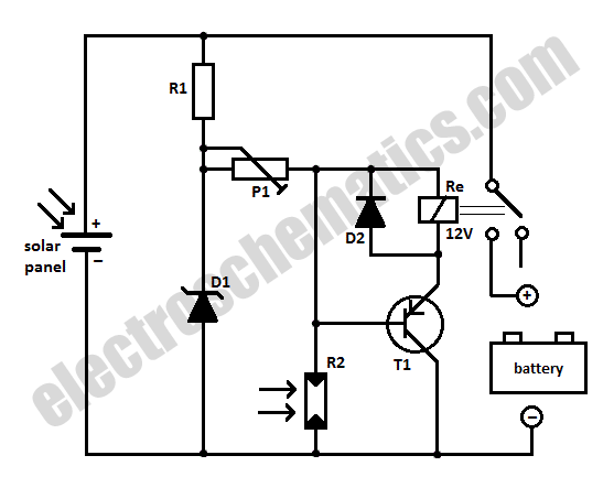
When charging a battery during the day using a solar panel, there is a risk of the battery partially discharging through the panel after sunset. This solar panel power switch circuit eliminates the need for a diode by utilizing...
The motors will be powered by the full source voltage, so it is important to ensure that this does not cause the robot to operate too quickly. The Firebot utilizes GM3 motors powered by a 9V battery; however, in...
The circuit for the solar-powered controller includes a switching circuit, a pulsing circuit, and a high-voltage output circuit. The external power components consist of a 1- to 5-W solar panel and a 12-V motorcycle or camcorder battery. The output...
These are operational amplifier (op-amp) based filters that are particularly effective within the audio frequency range. The calculators for these filters utilize formulas and tables from the book "Electronic Filter Design Handbook" by Arthur B. Williams. Bandpass filters allow...
The ultimate source of energy is the Sun. It is possible to generate current from sunlight using solar panels. These panels convert light energy into electrical energy. A solar panel consists of a number of solar cells, which produce...
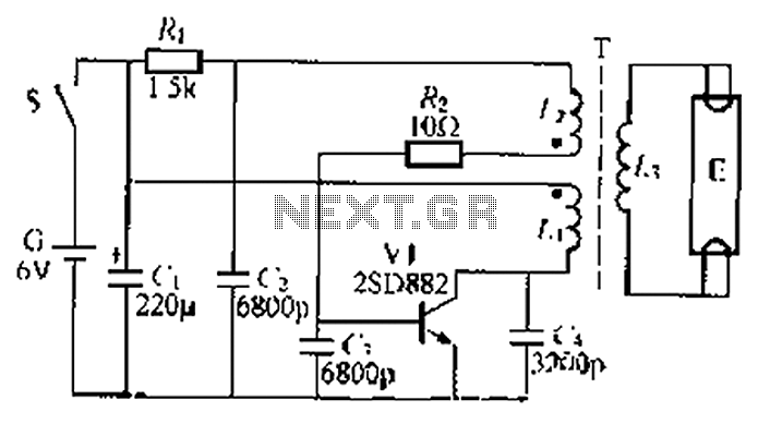
The circuit described is a battery-powered fluorescent lamp system designed for temporary emergency lighting during power outages. It utilizes a transistor (V7) and a boosting transformer (T) along with an inductive feedback oscillator to generate a high-voltage output. When...