
mosfet prevents battery damage
.jpg "mosfet prevents battery damage")
The described circuit operates effectively to ensure the integrity and safety of sealed lead-acid batteries in various power electronics applications. The use of a diode provides a basic level of protection; however, its limitations necessitate the inclusion of an N-channel MOSFET for enhanced safety. The MOSFET acts as an electronic switch, allowing current to flow only when the battery is connected correctly. This is critical in preventing damage that could occur from incorrect battery connections, which can lead to excessive currents and potential thermal runaway situations within the battery.
When the circuit is powered, and the battery is connected correctly, the forward biasing of the transistor allows the MOSFET to turn on, facilitating the charging of the battery while simultaneously powering the load. In contrast, if a reverse connection is detected, the MOSFET switches off, effectively isolating the battery from the charger circuit and the load. This action prevents any reverse currents from damaging the battery or the charger components.
Incorporating a microcontroller into this setup allows for real-time monitoring of the battery's state, including voltage and current levels. The microcontroller can be programmed to execute specific actions based on the battery's condition, such as triggering alarms for abnormal conditions, initiating protective measures, or adjusting the charging parameters to optimize battery life. This integration enhances the overall functionality and safety of the power electronics system, making it more adaptable and reliable in various operational scenarios.Sealed-lead-acid batteries, which find wide use in power-electronics products, such as UPS (uninterruptible-power supplies), inverters, and emergency lamps, supply power to the load whenever utility power is unavailable. When you restore utility power, a charger supplies the power to the load and charges the batteries (Figure 1).
You can add a dio de to protect a load from current resulting from a reverse-connected battery. The diode, however, won`t protect a reverse-connected battery from the charger circuit. If the charger is on, a potentially dangerous current can flow into a reverse-connected battery. The battery voltage, which normally opposes the charging voltage, now aids it, which lets a higher current flow into the battery. If you add an N-channel MOSFET to the circuit, you can protect the battery from this damaging condition (Figure 2).
The MOSFET conducts only when the battery is correctly connected, which lets the battery charge or discharge. In this condition, the transistor gets forward-biased, which switches on the MOSFET. If the battery is reverse-connected, the transistor and MOSFET turn off, thus preventing current flow.
This simple circuit provides reverse-battery protection in both charger and battery paths, thereby protecting the battery, the charger, and the load. You can use a microcontroller to measure battery current and make a decision on appropriate action, as well.
🔗 External reference
Related Circuits
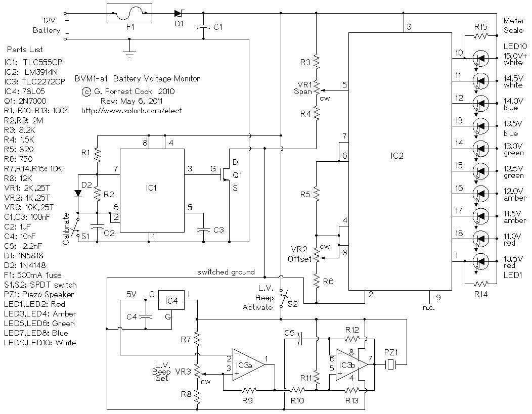
This circuit provides an audible and visual low voltage warning for 12V battery powered devices. When the battery voltage is above the set point (typically 11V), the circuit is idle. If the battery voltage should fall below the set...
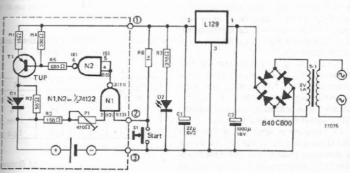
The maximum charge voltage is set at 1.45 volts, while the higher trigger threshold is approximately 1.7 volts. This voltage can be adjusted using potentiometer P1 to reach 1.45 volts. A TTL control signal is output by the voltage...
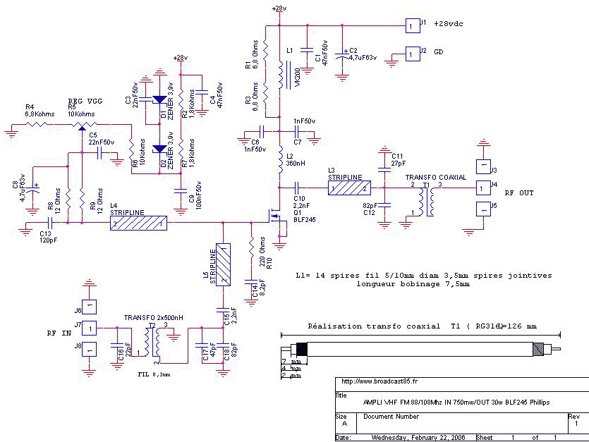
The achievement of this 30 watt amp was thought to take place on a heatsink microprocessor PC. Equipped with its fans, the advantage of this method of cooling was chosen for the fact it is common and not very...
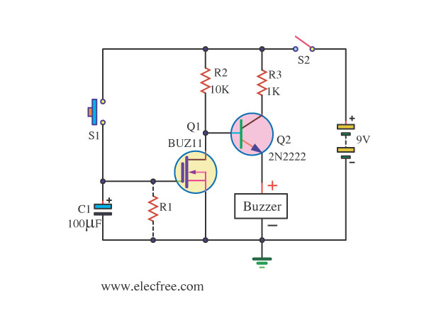
This is an On After Delay Circuit. It utilizes a MOSFET in the circuit for easier delay implementation compared to using a transistor. The operation of the circuit begins when switch S1 is pressed. The On After Delay Circuit is...
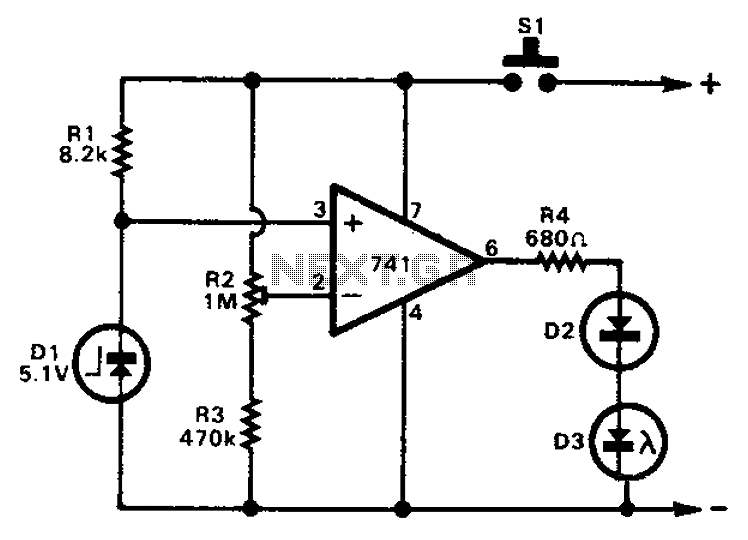
The 741 operational amplifier can function as a voltage comparator. It features a non-inverting input and a Zener-controlled voltage source, with a reference voltage set at 5.1V. Resistor R2 is used to adjust the in-phase input voltage to half...
This is a low-cost universal battery charger circuit. This circuit is designed to charge NiCd and NiMH batteries and is ideal for use in vehicles. The circuit converts mains voltage. The low-cost universal battery charger circuit is engineered to efficiently...