
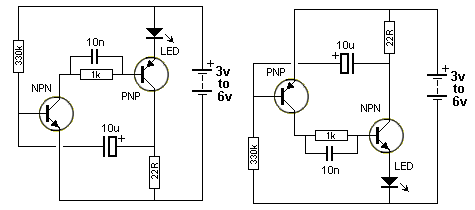
Light flashing circuit
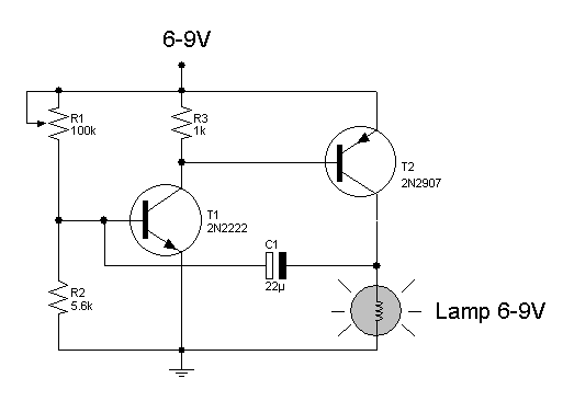
The light flashing circuit typically consists of a few key components: a power source, a lamp (LED or incandescent), a resistor (R1), and a timing element, which can be a capacitor and a transistor or an integrated circuit (IC) designed for timing applications.
In this configuration, the resistor R1 is crucial for controlling the current flowing to the lamp. By adjusting R1, the voltage across the lamp can be varied, effectively changing the brightness and the flashing rate. The timing element, often implemented with a capacitor (C) and a transistor, establishes the timing cycle. The capacitor charges and discharges through R1, creating a time delay that results in the one-second flashing interval.
For a basic implementation, a common timing circuit can be based on a 555 timer IC configured in astable mode. In this setup, the 555 timer generates a square wave output, which can be used to drive the lamp. The frequency of the oscillation is determined by the values of R1, R2 (another resistor), and C.
The standard formula for calculating the frequency (f) of the output signal in an astable 555 timer circuit is given by:
f = 1.44 / ((R1 + 2 * R2) * C)
By selecting appropriate values for R1, R2, and C, the desired flashing rate can be achieved. Adjustments to R1 allow for fine-tuning of the flash rate while maintaining the overall functionality of the circuit.
Safety considerations should be taken into account, especially when working with higher voltages or currents. Proper heat dissipation methods for the lamp and the components should be ensured to prevent overheating and potential damage.
This light flashing circuit can be applied in various applications, such as decorative lighting, signaling devices, or as an attention-grabbing indicator in electronic projects.Light flashing circuit.
Related Circuits

This circuit is a wireless car alarm system constructed using two modules: a transmitter module and a receiver module. It operates on FM radio waves and is suitable for vehicles with a power supply of 6-12VDC. A voltage stabilizer...
The circuit involves powering an LED using a 3V CR2032 battery, with the intention of extending battery life by making the LED blink rather than remain continuously on. A 555 timer is considered, utilizing large value resistors in the...

The BISS0001 is a high-performance integrated circuit designed for sensor signal processing. When combined with pyroelectric infrared sensors and a minimal number of external components, it forms a passive pyroelectric infrared switch. This device can automatically and quickly activate...

A distortion circuit is being developed utilizing a single 12AU7 tube configured as a diode. The design is acknowledged as basic, intended primarily for the purpose of adding distortion effects. The proposed circuit leverages the 12AU7 vacuum tube, which is...
The circuit can also be triggered by logic ICs (TTL/CMOS) using the appropriate interfacing method. Another relay is typically used to serve as the trigger button when interfacing ICs with the latching relay circuit. The described circuit utilizes a latching...

The ordinary triode 3DA87C is utilized to create a long-range FM transmitter circuit, which functions as a standard three-point oscillator circuit. This remote transmitter circuit is capable of large current emissions, achieving a range of up to 1 kilometer...