
Fluorescent energy-saving electronic ballast circuit
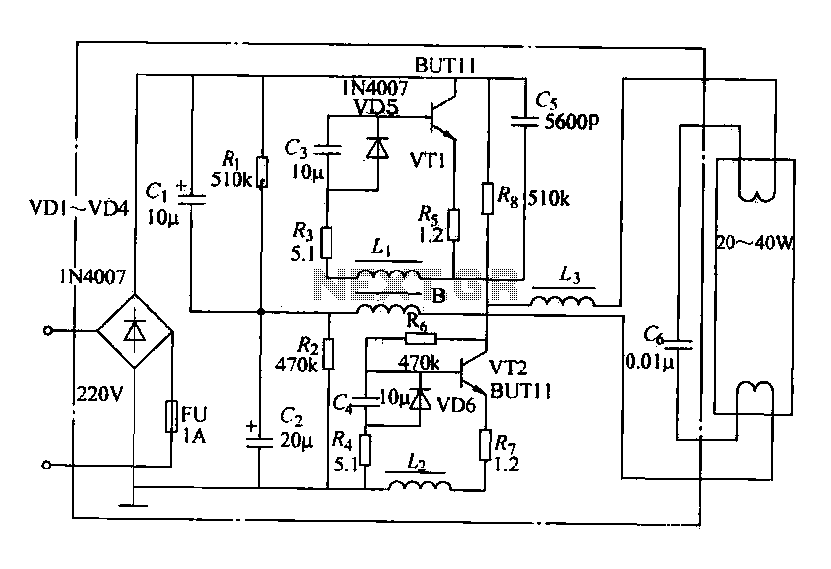
The electronic ballast circuit is designed to efficiently drive fluorescent lamps by converting high-voltage AC to a stable DC voltage, which is crucial for maintaining consistent lamp performance. The bridge rectifier formed by diodes VD1 to VD4 ensures that the AC input is rectified into DC, while capacitor C1 smooths out the rectified output, reducing voltage ripple and providing a stable supply voltage for the subsequent stages.
The startup winding resistance plays a critical role in providing the necessary bias voltage to transistor VT2. This biasing is essential for initiating the oscillation process in the circuit. Once the circuit is energized, VT1 and VT2 work together to produce high-frequency oscillations, which are essential for efficiently driving the lamp. The self-oscillation mechanism allows the circuit to adapt to varying load conditions and maintain optimal performance.
Inductor B is employed for buck conversion, which is a method of reducing the voltage to a desired level while increasing the current. This is particularly important in applications where the lamp requires a specific operating voltage that is lower than the input voltage. The energy stored in the inductor during the on phase is released to the load during the off phase, ensuring that the lamp receives the necessary power without excessive energy loss.
The soft-start circuit, composed of components C3, VD5, VD6, and G, is designed to gradually apply power to the lamp. This gradual increase in voltage helps to preheat the lamp filaments, which is crucial for ensuring a successful ignition. By delaying the establishment of the operating point, the circuit minimizes the thermal shock to the lamp, thereby extending its lifespan and improving reliability.
Overall, the electronic ballast circuit represents a sophisticated approach to lamp driving technology, combining efficiency, reliability, and user-friendly features such as quiet operation and flicker-free light output.Electronic ballasts have a wide operating voltage range, fast start working no noise, no flicker, save energy and so on. It has been more and more people to accept. The circuit shown in FIG is currently available on popular electronic ballast typical circuit. Figure 10-3, VD1 ~ VD4, c1, G form a bridge rectifier and filter circuit, complete 300V AC-to-DC conversion zzov. Horse, start-up wind resistance, to provide turn-VT2 bias voltage, thereby stimulating VT1, VTZ formed high-frequency self-oscillation.
B for the buck produce self-inductance choke, C3, VD5, VD6, G composition soft-start circuitry, so that the establishment of the circuit operating point to the delay, so that the lamp filament preheating plus long, in order to facilitate the rapid start lamp, extending its life.
Related Circuits
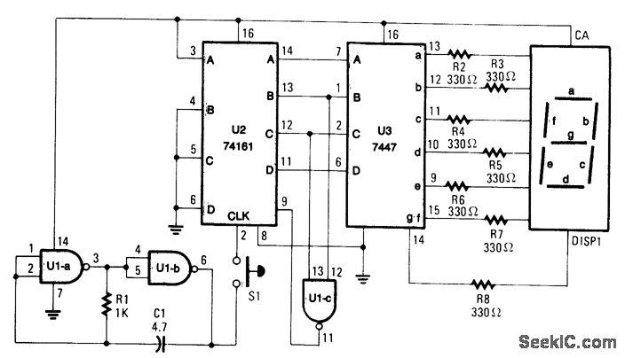
When S1 is pressed, counter U2 is activated by oscillator U1A/U1B, and the count (ranging from 0 to 6) is displayed on DISP1. The resistor R1 and capacitor C1 define the count rate, which must be sufficiently rapid to...
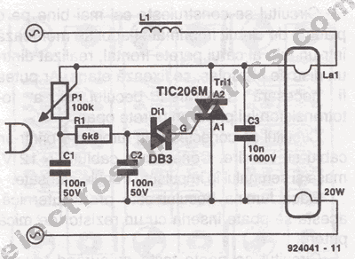
The brightness of a fluorescent light bulb or neon tube is not as easily adjustable as that of an incandescent bulb because it requires a much higher voltage to start. Once initiated, it operates at the electrical network voltage....
The resistors were not measured precisely, and given their ±5% tolerance, along with a Vref range of 1.2 to 1.3 volts, it is possible to exceed 6 volts in certain scenarios. A discussion arose regarding the effectiveness of these...
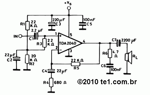
The TDA2040 is a monolithic integrated circuit housed in a Pentawatt package, designed for use as an audio class AB amplifier. It typically delivers an output power of 22W (with a distortion factor of 0.5%) at a supply voltage...
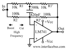
This discussion continues from the audio tone control topic, which introduced both passive and active tone controls. The follow-up topics may include a 2-Band Active Tone Control or a 3-Band Active Tone Control. An audio equalizer is utilized to...
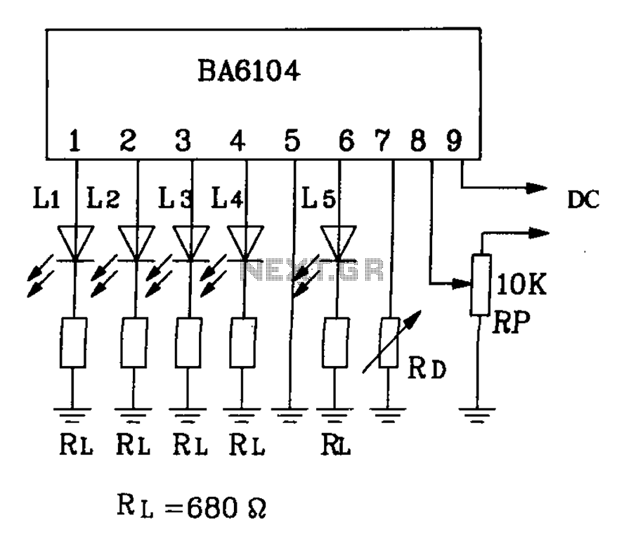
BA6104 is a five-digit LED level meter driver integrated circuit (IC) that features a basic application circuit. The input stage employs a PNP transistor with a composite base input, resulting in high input impedance. The output stage is configured...
Warning: include(partials/cookie-banner.php): Failed to open stream: Permission denied in /var/www/html/nextgr/view-circuit.php on line 713
Warning: include(): Failed opening 'partials/cookie-banner.php' for inclusion (include_path='.:/usr/share/php') in /var/www/html/nextgr/view-circuit.php on line 713