
Live Wire Antenna
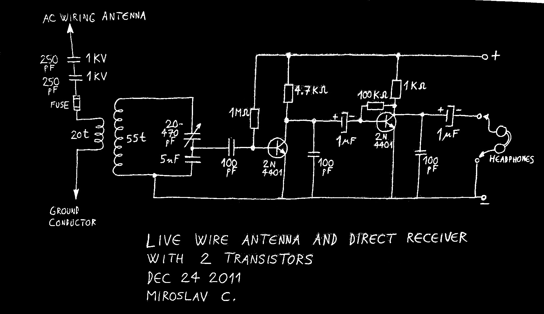
The circuit design involves a medium-wave AM receiver utilizing two transistors, configured to demodulate and amplify the incoming radio signals. The receiver's front-end consists of a resonant LC circuit, which is tuned to the desired frequency range. The use of a capacitive divider allows for the extraction of high-frequency signals while minimizing loading effects on the LC tank circuit. The variable capacitor in the divider provides a means to adjust the resonant frequency, optimizing reception across the medium-wave band. The safety measures implemented, including high-voltage capacitors in series and a fuse, are essential for protecting both the circuit and the user from potential high-voltage spikes. The design considerations reflect an understanding of RF principles and safety protocols, making it a practical solution for amateur radio enthusiasts facing limitations in antenna installation.Using live or neutral wire in AC household wiring as receiving antenna. Of course, this is possible only with high voltage capacitor inserted between the receiver antenna terminal and live or neutral wire. AC wiring antenna solution was mentioned as some type of last resort, when no other antenna can be installed due to space contraints.
Ground conductor can be used as Earth ground. Old books recommend cold water pipe as ground connection, but I`m not sure whether this is good/practical/allowed any more. They also recommend "one good condenser" for antenna connection, not 2 in series. I guess people were braver then :) I decided to test this system myself. I made a small 2-transistor medium-wave AM receiver, with headphone output. To reduce main LC tank circuit loading, HF is taken from a capacitive divider of variable cap and 5 nF cap.
Smaller voltage drop exists on larger capacitor due to its smaller capacitive reactance Xc=1/(2*pi*f*C). Voltage taken from main LC circuit decreases as higher frequencies are received: smaller capacitance of variable cap takes on more of capacitive divider voltage.
This was deemed to be unimportant for fairly narrow range MW tuning. Received high frequency is demodulated at the base of first transistor and then amplified as low frequency in the first and second transistor. Calculated frequency range is approximately 700 kHz - 2800 kHz. To protect myself and my receiver, I decided to use two high voltage capacitors in series, antenna coil galvanically separated from remainder of circuit, and fuse.
If high voltage spike is somehow able to penetrate through both 1 kV rated capacitors, it will blow open the fuse. Failing that, antenna coil (0. 3 mm diameter wire, 20 turns) will burn out, with no further damage done to receiver (or user). Hopefully. :) Several tests were done: first with 1 m wire antenna, without ground connection. Four nearby AM stations were received, 3 were identified for testing. Latter tests were done with live wire antenna connected to AC outlet, neutral wire antenna connected to AC outlet, and lastly power cable antenna NOT plugged into the outlet.
Testing video with live wire as antenna. Antenna is plugged into the AC outlet during the video. This changes main receiver LC circuit frequency somewhat, so re-tunning is necessary for maximum sound output. Sound is weak because it is coming from the headphones only, so weaker stations cannot be heard in the video.
Fourth station received and understandable, but not used for testing, was 820 kHz CHAM, 15 km distance to TX, 30 mV at headphones, 50 kW TX. Measured with live wire antenna, Earth connection to grounded cable conductor, cable NOT plugged into AC outlet.
Regular 6 feet (1. 8 m) power cable, even when not plugged into the outlet, provides surprisingly good reception, much better than just single 1 m wire. I suspect this has something to do with the fact that antenna and ground wire are identical in length, which makes it into a crude non-resonant dipole antenna (but with parallel arms instead of 180 degree arms).
Or not. Live wire / neutral wire antenna connections provide a lot of usable signal, so my judgment is that this is a viable way to have some antenna if nothing else is available. Main problem: 60 Hz hum that masks weak stations. It could be reduced in two ways: Use smaller number of turns for antenna coil. 20 is way too much, 5 will do just fine. It will provide better impedance mat 🔗 External reference
Related Circuits
The water resource is being transformed into a valuable and rare commodity. Consequently, promoting water-saving irrigation has become a priority for countries worldwide to address the water resource crisis and achieve agricultural modernization. This text proposes a cipher scheme...
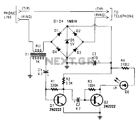
The IR transmitter connects to a telephone circuit and transmits both sides of all telephone conversations to any line-of-sight location within 40 feet. No power is drawn from the central office, as long as all phones remain on-hook. The...
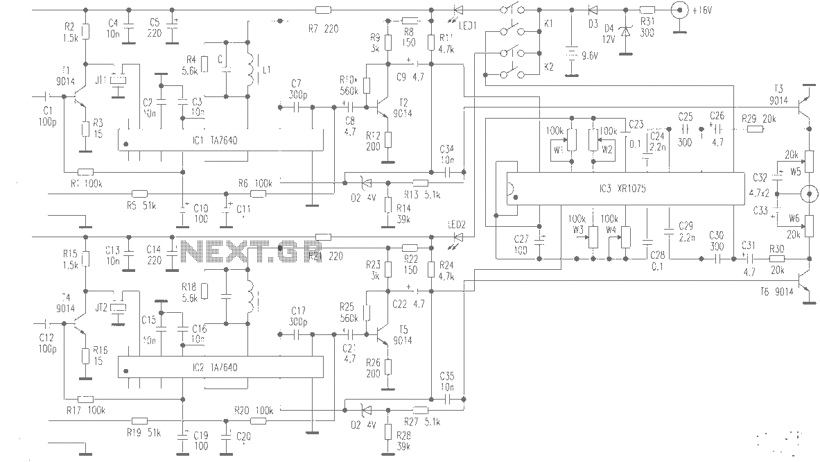
The production of high-quality wireless microphones is a common aspiration among enthusiasts, but achieving a high-performance receiver is challenging. This project explores the use of salvaged FM radio cassette players to enhance an XR1075 audio processor, leading to the...
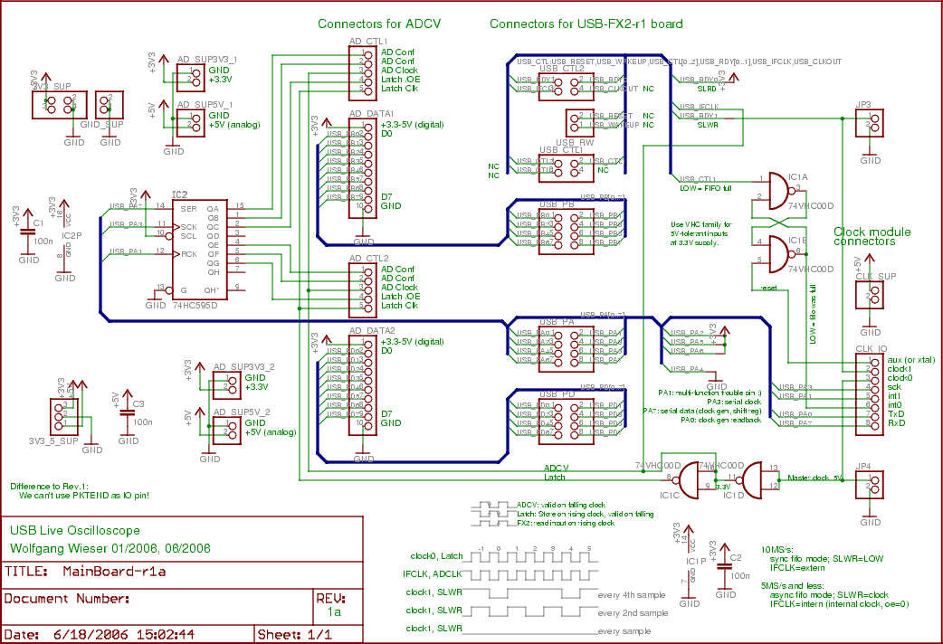
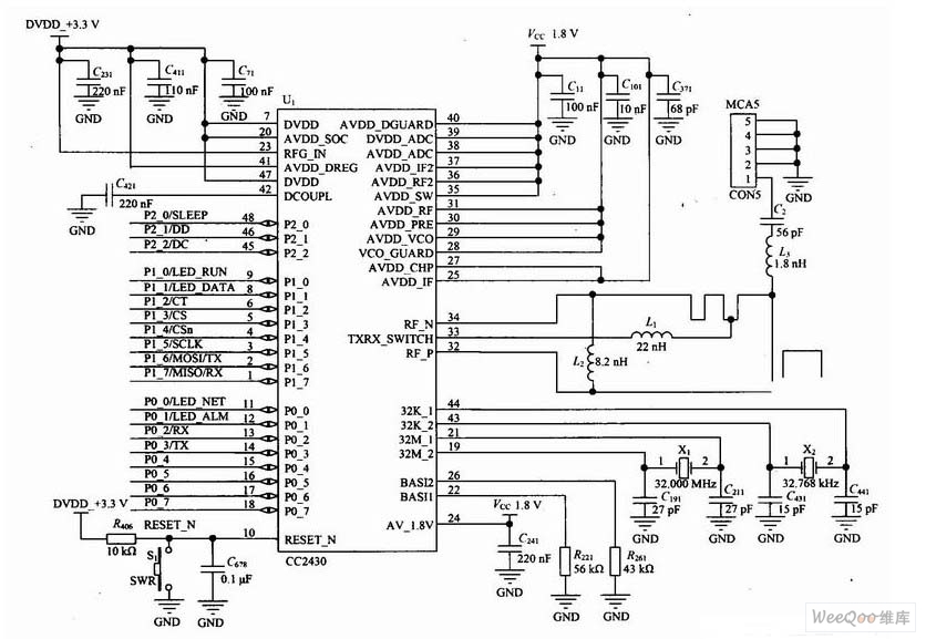
The two input boards (ADCV or digital) are connected to AD_CTL1, AD_DATA1, AD_SUP5V_1, and AD_SUP3V3_1 for the first board, with the second board using the same connections but with a suffix of 2. To transfer sampling data, the 16...
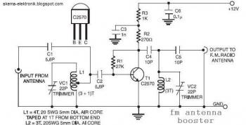
The input coil L1 is composed of four turns of 20 SWG enamelled copper wire, wound slightly spaced over a 5 mm diameter former. It is tapped at the first turn from the ground lead side. Coil L2 is...
The loop can be any type of hookup wire, with a maximum resistance of about 90K. Using very thin wire (40AWG, for example) will create a highly sensitive trip wire, but will reduce the distance it can be strung...