
FM Antenna Booster Circuit
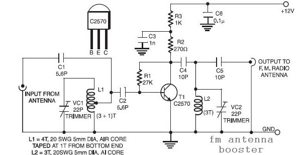
The FM antenna booster circuit is designed to enhance the reception of FM radio signals, particularly from distant stations. This circuit typically includes a few essential components: an operational amplifier (op-amp), a matching network, and a power supply.
The operational amplifier serves as the core of the circuit, amplifying the weak signals received by the antenna. The input stage of the op-amp is configured to optimize the signal-to-noise ratio, ensuring that the desired FM signals are amplified without introducing significant noise.
The matching network, which may consist of inductors and capacitors, is crucial for impedance matching between the antenna and the op-amp. This network helps to maximize power transfer and minimize signal reflection, thereby improving overall reception quality.
Power supply requirements for the circuit can vary, but it is generally designed to operate with low voltage DC sources, making it suitable for battery operation or connection to wall adapters.
In practical applications, the FM antenna booster can be connected directly to an existing FM antenna or can be used with a dedicated antenna designed for enhanced performance. By improving the signal strength and clarity of the received FM broadcasts, this circuit allows users to enjoy a broader range of stations and improved audio quality.
Overall, the low-cost FM antenna booster circuit is an effective solution for enhancing FM radio reception, particularly in areas where signal strength is weak or obstructed.This is a low cost fm antenna booster that can be used to listen to programmes from distant FM stations clearly. The antenna fm booster circuit comprises a.. 🔗 External reference
Related Circuits

This circuit is designed for lamp dimming and similar applications. It requires only one RC phase lag network. To prevent the hysteresis (or "snap-on") effect, the capacitor is reset to approximately 0 volts at the end of every positive...
This is a programmable clock timer circuit that utilizes individual LEDs to display hours and minutes. Twelve LEDs can be arranged in a circular pattern to represent the 12 hours on a clock face, while an additional 12 LEDs...
This version sports a 2nd audio amplifier stage at Q3. The output level with this version is sufficient to drive a crystal headphone to a comfortable volume. The "crystal" headphone is like those used on ye olde crystal radios....
A two-tone generator that is alternately switched ON provides a high/low output similar to that of a traffic vehicle, such as a police car or ambulance. The CD4011 integrated circuit (IC1), which is a quad 2-input NAND gate, functions...
In the event of a sudden power failure in an elevator, it is crucial for the duty officer in the distribution room to be alerted promptly to prevent panic among passengers trapped inside. The following describes a sound alarm...
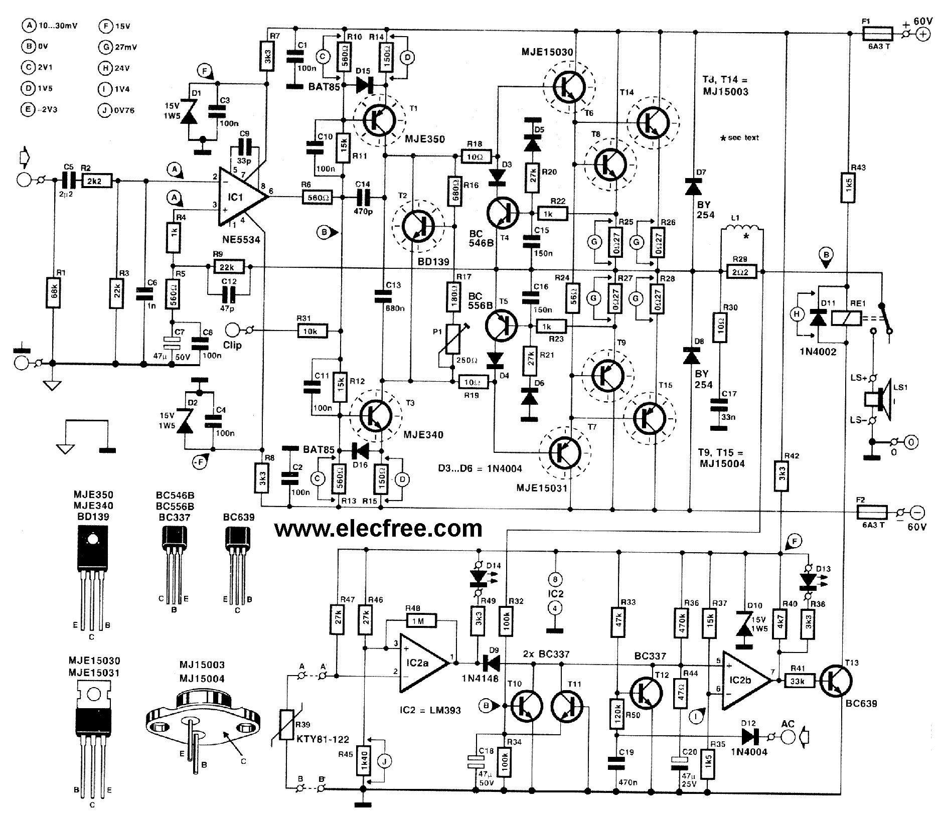
This circuit is designed for friends who are interested in high-power amplifier circuits. It can deliver approximately 300 Watts RMS and operates as an OCL (Output Capacitor-Less) Class AB amplifier, providing high sound power while systematically protecting the loudspeaker...