
FM Booster~Active FM Antenna Amplifier
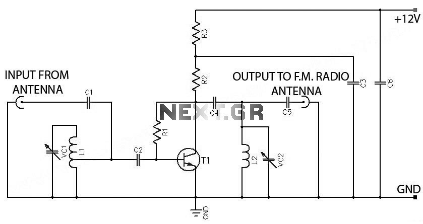
The FM booster circuit is designed to enhance the reception of FM signals from distant stations by amplifying weak radio frequency signals. The primary component of this circuit is the VHF/UHF transistor 2SC2570, which operates in a common-emitter configuration. This configuration is advantageous for RF amplification as it provides a good balance of gain and bandwidth.
The circuit typically includes several key components: an input matching network, a tuned circuit for frequency selection, and a power supply circuit. The input matching network is designed to optimize the impedance seen by the antenna to maximize signal capture. The tuned circuit, often consisting of an inductor and a variable capacitor, allows for selective amplification of the desired FM frequency while filtering out unwanted signals.
Power supply requirements for the 2SC2570 transistor should be carefully considered, as it operates efficiently within a specific voltage range. The circuit may also incorporate bypass capacitors to stabilize the power supply and improve performance by reducing noise.
Additionally, it is essential to ensure proper grounding and shielding of the circuit to minimize interference from external sources. The layout should be compact to reduce losses and maintain signal integrity. The output of the amplifier can be connected directly to an FM receiver or a further processing stage, depending on the application.
Overall, the FM booster circuit utilizing the 2SC2570 transistor is a robust solution for improving FM radio reception, particularly in areas with weak signal strength.FM Booster, Active FM Antenna Amplifier This FM booster that can be used to listen to programmes from distant FM stations clearly. The circuit comprises a common-emitter tuned RF preamplifier wired around VHF/UHF transistor 2SC2570.
(Only C.. 🔗 External reference
Related Circuits
Field strength meters are essential tools for individuals working with radio transmitter electronics. The following is an example of a circuit that serves this purpose. A field strength meter circuit typically consists of several key components, including an antenna, a RF...
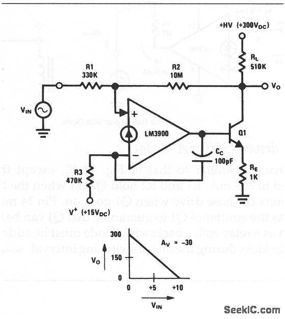
This circuit is an inverting amplifier with an output voltage swing from approximately 0 to +300 V. Any transistor can be utilized for Q1, as long as the breakdown voltage exceeds 300 V (since the full high voltage will...
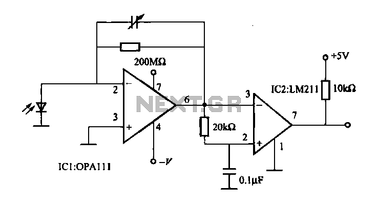
The OPA111 optical receiver amplifier features a feedback resistor of 200 MΩ, which is crucial due to the high gain of the amplifier. The OPA111 is designed to receive signals transmitted over optical fiber, specifically at a rate of...
This is a simple microphone preamplifier circuit which you can use between your microphone and stereo amplifier. This circuit amplifier microphone suitable for use with normal home stereo amplifier line/CD/aux/tape inputs. This microphone preamplifier can take both dynamic and...
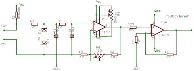
The OP07 operates as a non-inverting amplifier to avoid loading the millivolt signal from the thermocouple. Zener diodes are included to protect the circuit in the event of a failure in the junction contacts, heaters, or ground. A resistor-capacitor...
The amplifier of circuit uses negative current feedback. The load current depends mainly on the input signal and not so much on the impedance of the loudspeaker. The inductor current of the loudspeaker develops a voltage across R7. This...
Warning: include(partials/cookie-banner.php): Failed to open stream: Permission denied in /var/www/html/nextgr/view-circuit.php on line 713
Warning: include(): Failed opening 'partials/cookie-banner.php' for inclusion (include_path='.:/usr/share/php') in /var/www/html/nextgr/view-circuit.php on line 713