
simple thermocouple amplifier
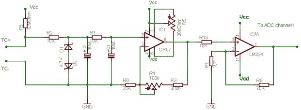
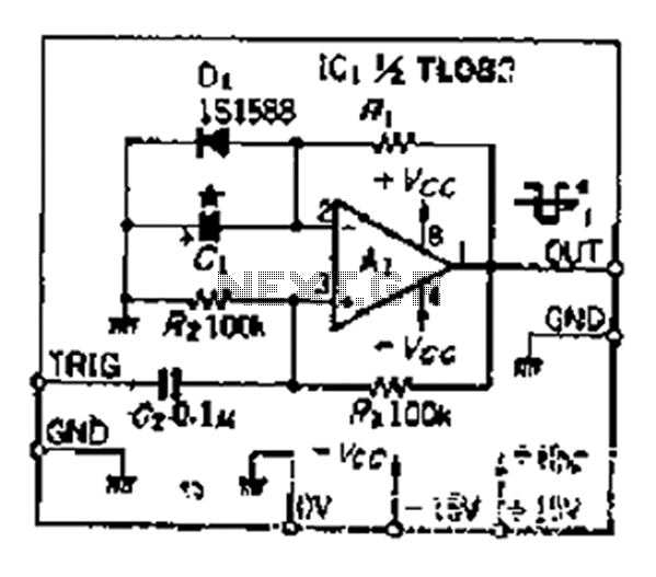
The circuit comprises several key components that work together to ensure accurate temperature measurement and control. The OP07 operational amplifier is chosen for its low offset voltage and high precision, making it suitable for amplifying the low-level signals from thermocouples. The non-inverting configuration allows the amplifier to provide a high input impedance, which is essential to avoid loading the thermocouple and altering its output voltage.
The inclusion of Zener diodes serves as a protective measure against voltage spikes that could occur due to faults in the system. These diodes clamp the voltage to a safe level, preventing damage to the sensitive components of the circuit. The RC filter is strategically placed to mitigate electromagnetic interference (EMI) from surrounding AC power sources, particularly in environments where heaters are present. This filtering ensures that the output signal remains stable and reliable, even in the presence of noise.
The pull-up resistor plays a crucial role in defining the output state during a thermocouple failure. By pulling the output to a defined high level, the circuit can trigger safety mechanisms in the control software, thus preventing potential overheating or damage to the system.
The second operational amplifier in the configuration allows for additional gain, enhancing the overall sensitivity of the temperature measurement system. Careful adjustment of the gain and offset is necessary to maintain accuracy, particularly when working with high gains. If higher gains are required, alternative amplifier types, such as instrumentation amplifiers, can provide better performance without the complications associated with offset adjustments.
Overall, this circuit design is tailored for industrial temperature control applications, where precision, reliability, and safety are paramount. The combination of operational amplifiers, filtering, and protective components creates a robust system capable of handling the challenges presented by thermocouple measurements in demanding environments.The OP07 is in a non inverting amplifier so as not load the mV of thermocouple, the zeners are to protect circuit if junction contacts heaters or the earth gets broken. The RC is to filter out 50Hz pick up in thermocouple wires if near heater wiring and also reduces reading jumps when high current three phase contacter operates.
The Pull-up 10M is when a Thermocouple breaks the output of circuit will be max. This is open sensor protection, in case Thermocouple breaks, Required only in industrial temperature controllers for protection. This means it will be 3. 5V which should make you turn off the heater in software. The other opamp is for further amplification as OP07 is set to around 30 gain and offset has to be adjusted with R9.
If OP07 is kept in > 100 gain it may be difficult to adjust offset of 75uV. If you need very high gain in the first stage use some instrumentation amplifier or chopper stabilized amplifier. I am not very sure. 🔗 External reference
Related Circuits
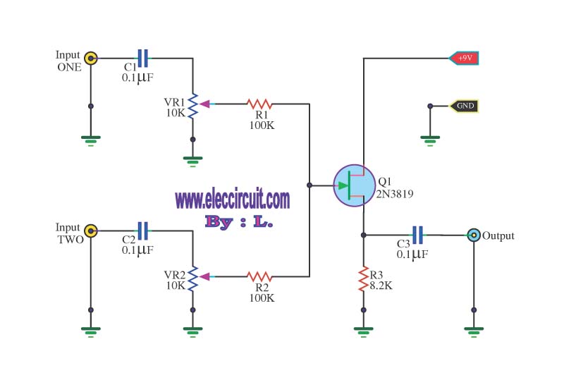
This circuit is a simple mixer circuit that can mix two signal channels into one output channel. It utilizes a codec circuit to convert stereo audio to mono audio. The main component in this circuit is a FET, specifically...
This is a microphone preamplifier designed for compatibility with a SoundBlaster AWE 64 sound card. It is also suitable for any compatible tag or PC audio input that provides a 5 Volt supply through a 2.2kΩ current-limiting resistor located...
Individuals seeking private listening to their music should incorporate this Headphone Amplifier into the Modular Preamplifier chain. The circuit design prioritizes simplicity while ensuring high-quality performance. This objective is achieved through the use of two NE5532 Op-Amps, where IC1B...
Output-clamp diodes are mandatory because loudspeakers are inductive loads. Output LR isolation is also used because audio amplifiers are usually expected to handle up to 2 mF load capacitance. Large, supply-bypass capacitors located close to the IC are used...
The circuit depicted in Figure 5-60 and Figure 6 utilizes an operational amplifier (op-amp) configured as a channel pre-amplifier to address the signal loss introduced by the tone control circuit. Additionally, another group of op-amps forms a channel-driven stage...
Although people believe that using a timer with an operational amplifier (op-amp) does not yield significant results, it can still be advantageous in certain scenarios. In environments with high noise levels, the application retains its benefits. When the phase...