
fm bug
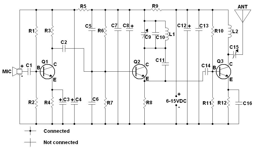
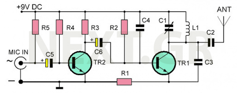
The FM wireless microphone circuit employs a straightforward design utilizing three transistors, typically configured in a common emitter arrangement to amplify the audio signal from the microphone. The circuit operates within the FM frequency range, allowing for efficient transmission of audio signals. The choice of the 2N3904 transistor or its equivalents ensures that the circuit can operate effectively at the required frequencies due to their high transition frequency (Ft).
The construction of the coil L1 is a critical aspect of the circuit's performance. The specified method of wrapping wire around a smooth rod allows for precise inductance values, which are essential for tuning the circuit to the desired frequency. The adjustment of the coil's turns directly impacts the resonant frequency, making it vital for achieving optimal performance within the desired range.
The microphone's antenna configuration, consisting of a simple 9-inch length of wire, is designed to provide adequate transmission capability while keeping the design compact. The length and type of wire used for the antenna can significantly affect the transmission range and quality of the audio signal.
The modifications suggested for operating above the FM broadcast band allow for versatility in application, enabling the use of the microphone for various purposes, including experimentation with VHF communication frequencies. However, users must be aware of the legal implications of operating in these bands and ensure compliance with local regulations.
In summary, this FM wireless microphone circuit is a versatile educational project that demonstrates fundamental principles of RF transmission and audio amplification. Proper construction, adherence to specifications, and awareness of legal constraints are essential for successful implementation.A simple little three-transistor FM wireless microphone / room bug that can really throw-out quite a signal. With a wide tuning range from 80 MHz to 120 MHz, this little device can transmit anywhere within the FM broadcast band (88 to 108 MHz) and can be heard with any standard FM broadcast receiver.
A simple modification (described below) allows the mike to operate above or below the FM broadcast band. Transmission is line-of-sight, so radius of coverage and be anywhere from 300 feet (indoors, with 9" wire antenna) up to 1 km or more using a properly matched 1/4 wave monopole ground plane antenna on a rooftop in the open countryside. For best results, I built this project on a 2. 5" x 3. 5" printed circuit board. Schematic diagram, printed circuit pattern and component layout diagram are shown below. Warning: This device is for educational purposes only! It is NOT to be used as a bug. Please keep experiments legal. It is your responsibility to check with local law authorities to determine the legal implications if you use this device.
Information on this page is provided as a courtesy for educators, students, and hobbyists. Feel free to printout digrams and parts list for you own use. This page isn`t going anywhere, so you may bookmark this page for later use if you have a del. icio. us account. Note: This microphone was built as part of a school project when I was a kid, which was FCC Part 15 compliant at the time. This may or may not be the case today. I no longer have the project with me as it had been damaged (connected to an HV power supply in error, accidentally "frying" the parts with 200 volts DC!).
For best results, the FM wireless microphone should be built on a printed circuit board using the pattern shown above. Keep connections as short as possible (especially in the RF sections!), as excess lengths can introduce stray inductances and/or signal loss.
The 2N3904 transistors can be substituted with almost any small signal NPN transistor with an Ft rating of about 200 MHz or greater, such as a 2N2222, 2N2222A, PN2222, PN2222A, BC108, BC108A, etc. Coil L1 is by wrapping 4 turns of #18 coated enamel wire (cut to 4") around a 1/4" smooth rod or shank of a drill bit.
Remove the drill bit and stretch coil to 5/8" length. Remove 1/4" of insulation from both ends and solder to PCB and cut off extra length. Note the polarity of the condenser mike (fat prong is positive) and location of flat side of trimmer cap (see pictorial diagram). All transistors and electrolytic capacitors (marked with polarity on schematic) MUST be installed correctly or mike will not work.
The antenna (marked "ANT") in the original kit consists of a 9" length #18 enamel wire. Remove 1/4" of enamel insulation from one end and connect and solder this wire to the PCB hole marked "ANT". Cut off any excess lead length. With a simple modification, the wireless microphone can be made to transmit on the VHF "scanner frequencies" above or below the FM broadcast band.
Of course, this means you will not be able to tune-in on your mike with an ordinary AM/FM radio. To operate above 108 MHz, simply remove C10 and use a 3-turn coil for L1 instead of the 4-turn coil. This mod will enable the mike to transmit in and around the VHF "high band" region (i. e. 137 - 174 MHz) where many two-way radio services operate. However, unlike VHF communications services, in which narrow-band FM is used, your microphone transmits wideband FM like the standard FM broadcasts, therefore you will need to use a VHF receiver with an analogue slide-rule dial that can cover a region between above 108 MHz, such as a multiband radio with a weather band or a World War 2 vintage Hallicrafters model S-36A communications receiver if you are lucky enough to find one. If you use "police band" scanner, you will hear a lot breaking-up in the audio (if you have the noise squelched off) due to wide frequency swings.
To operate on 🔗 External reference
Related Circuits
Is a 100 to 200 metre (100 to 200yds) device having a very stable performance. It can be used as a hand held microphone or left on a shelf to pick up the sounds in a room. It has...
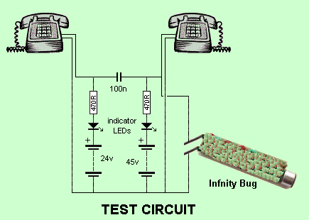
At this stage, a whistle is directed into the receiver, and the Infinity Bug will activate. The high-gain amplifier within the Infinity Bug captures audio from its location. It can only be assembled on the provided PC board since...
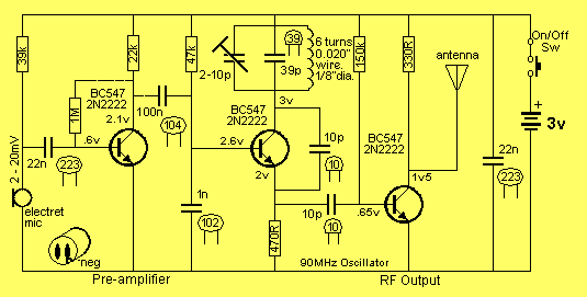
The circuit is basically a radio frequency (RF) oscillator that operates around 100 MHz. Audio picked up and amplified by the electret microphone is fed into the audio amplifier stage built around the first transistor. Output from the collector...
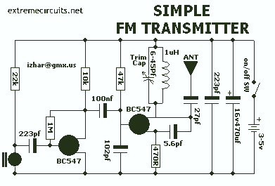
The recommended transmitter is straightforward to construct and suitable for beginners. Despite its simple design and compact size, it delivers remarkable performance. It operates for 12-15 hours on a 9-volt battery and has a transmission range of 100 to...
This device is designed for individuals concerned about surveillance. An essential tool for any operative is an Electronic Bug Detector, as it helps identify hidden listening devices. The Electronic Bug Detector serves as a critical instrument for privacy protection in...

This circuit represents an FM transmitter, also referred to as an FM Bug, which consists of 18 essential components for optimal functionality. The circuit begins with an electret microphone on the far left side, and the signal flows electrically...