
Infinity Bug
The Infinity Bug's design incorporates a high-gain amplifier to ensure effective audio capture, optimizing performance in various environments. The circuit is constructed with a focus on minimizing power consumption, particularly in the quiescent state, where the whistle-detecting circuit operates efficiently at a mere 0.25mA. The use of specific components, such as the BC 547 and 40106 IC, ensures that the circuit remains responsive to audio signals while maintaining stability against voltage fluctuations typical in telephone lines.
The bridge configuration on the front-end is a critical design element, allowing for versatility in installation while safeguarding against issues related to voltage reversal. This feature ensures that the Infinity Bug can function reliably in different phone line conditions without requiring complex adjustments. The careful selection of resistors and capacitors throughout the circuit contributes to its robustness, with particular attention given to the timing section, which employs a hex Schmitt trigger to manage transitions effectively.
Additionally, the inclusion of zener diodes and signal diodes enhances the circuit's ability to handle high voltages, such as the ring voltage, while protecting sensitive components from damage. The design also emphasizes the importance of impedance matching, facilitating seamless integration with the phone line and ensuring optimal signal integrity.
Overall, the Infinity Bug circuit represents a well-thought-out design that balances functionality, efficiency, and reliability, making it a valuable tool for audio detection applications.At this point you whistle into the receiver and the Infinity Bug will pick up the line. The high-gain amplifier in the Infinity Bug will pick up the audio at the place where it is located. It can only be assembled on the PC board supplied in the kit as the Latching Circuit is already soldered to the board and the project will not work with substit ute components. When the Infinity Bug is connected to the line, the "line voltage" will drop to about 36v, due to the current drawn by the bug. This will not upset the operation of the phone system. The bridge on the front-end allows the project to be connected either way around and allows for the annoying feature of some phone lines.
They create a voltage reversal as soon as the phone is picked up and this would defeat a Bug that requires a polarized voltage. The only two sections drawing current during quiescent conditions is the whistle-detecting circuit made up of the BC 547 and its surrounding components.
This section draws less than 0. 25mA. It is frequency sensitive and will not detect the 33Hz ring frequency. The other section is the "timing section, " made up of the 40106 IC. This is a hex Schmitt trigger (the same as 74C14). When a phone (that is connected to the same line as the Infinity bug) is picked up, the line voltage drops to about 12v and the whistle-detecting circuit does not see any voltage, as the 8v2 zener drops nearly all the available voltage. The transistor amplifies the signal to produce a 2v p-p signal that is turned into a DC voltage by the 10u.
This turns on the latch circuit and the base of the BC 639 is raised to produce a voltage on the emitter of about 4. 5v The actual voltage on the emitter of the BC 639 is determined by the 120R in the emitter leg of a BC 547.
The BC 547 is almost fully turned on by the 10k resistor between the collector and base. The transistor acts as an impedance-matching stage as the phone-line has a relatively low impedance while the pre-amplifier section has a quite-high impedance. Finally, the microphone is connected to microphone pre-amplifier stage consisting of a BC 547 transistor, 1M bias resistor, 4k7 load and 22n input capacitor.
The voltage across the IC is set to 6v2 via a zener so the timing can be controlled as the lower threshold at which the chip will change state is determined by the supply voltage. When the line voltage rises to 50v, the 47u in the timing circuit is rapidly charged via a 47k resistor that is connected to the rail via an 18v zener.
This put a maximum of 6v2 on the 47u as the input of the chip cannot rise above the supply on the chip due to diodes on the input of the gate. When the Infinity Bug is turned ON via a whistle, the line voltage falls to about 12v and the 47u in the timing circuit does not see any charging voltage as the 18v zener removes this voltage.
The 47u is now slowly discharged via a 2M2 and when the voltage falls to below 2v, the output of the gate goes HIGH. This HIGH is passed to the base of a BC 639 via a 22k and 1u electrolytic. The 1N4148 signal diode connected to the rail of the project is connected to a 22k and 100n. This arrangement detects the "ring voltage" (approx 150v) and the zener of the signal diode allows the 100n to charge via the 22k.
All diodes have a maximum reverse voltage and the diode we have chosen has a voltage of about 110v. This voltage can be called it "zener voltage. " Any voltage above this "zener voltage" will pass through the diode. We have used this feature to keep the whistle-detect transistor turned on during the time when the phone is "ringing. " There are a number of other features of the circuit contained within the Latching Circuit that allows the project to operate successfully, but these have been kept secret and are mounted on the PC board when a kit is purchased.
The surface-mount components are generally the first to be soldered to the board. But in this project, there are t 🔗 External reference
Related Circuits
The Bug-Eyed Eggliner project involves creating a whimsical animated figure with large, illuminated, and movable eyes. The project utilizes a combination of wooden balls for the eyes, a PICAXE microcontroller for control, and a servo mechanism to achieve eye...

This is the basic FM transmitter that I built. In theory, according to electronics, it shouldn't work but works fine and is very sensitive. It can transmit the signal up to 45 yards (about 40 meters). A sensitive FM...
This LCD terminal provides two modes of operation by selecting jumper J1. When J1 is open, the terminal operates as a normal ASCII display terminal; when J1 is closed, the terminal displays the input serial data in hexadecimal format....
Progress has been made on the project. Recently, a 6 kHz oscillator was constructed using a 555 timer to generate a clock signal for injection into the 832 unit. The output can be observed on an oscilloscope, and an...
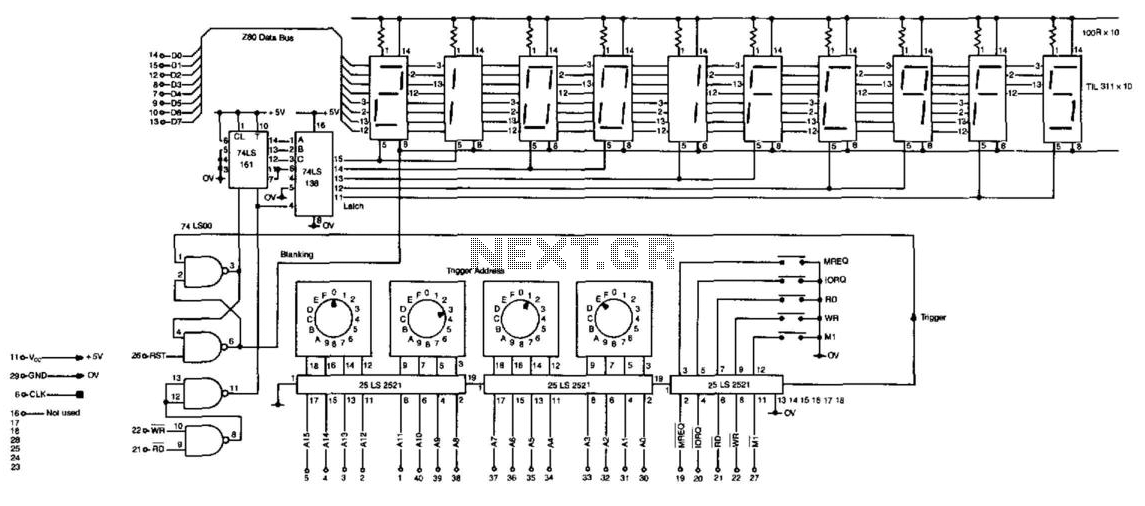
Getting microprocessor designs to function correctly is often challenging, particularly when both the software and hardware are unfamiliar. The typical method involves executing test routines that target memory and I/O without relying on their proper operation. However, any miswiring...
My FM Wireless Microphone has been a very popular project with beginners and experienced constructors alike. It has been used inside guitars and as the basis of a remote control system. I do however, receive many requests for a...