
Fm demodulator
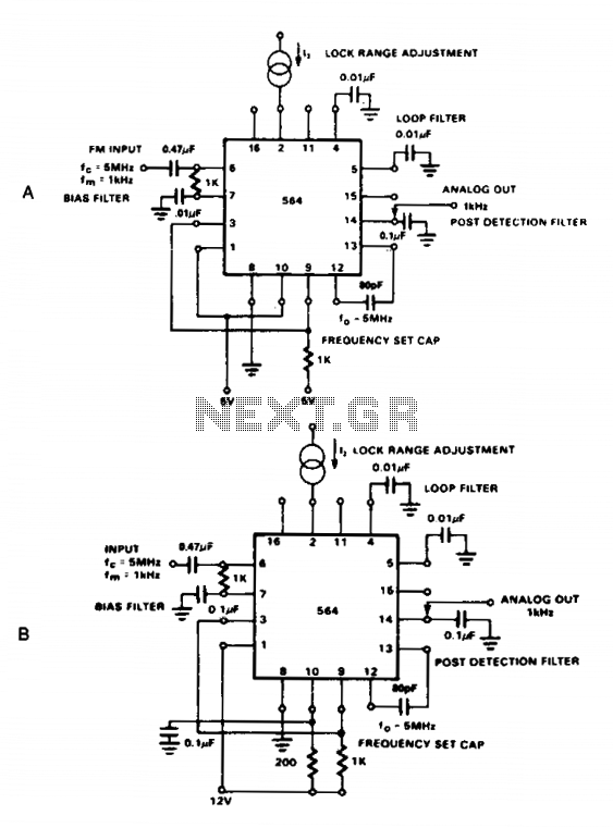
The NE564 is a versatile integrated circuit designed for frequency modulation (FM) demodulation applications. This device operates effectively in both low-voltage (5 V) and standard voltage (12 V) environments, making it suitable for various electronic systems. The AC coupling of the input signal is crucial, as it ensures that only the varying component of the signal is processed, eliminating any DC offset that could distort the demodulated output.
The output signal is taken from Pin 14, which is strategically designed to provide a clean demodulated output. Loop filtering is a critical aspect of the NE564's operation, as it stabilizes the demodulation process and enhances signal integrity. Capacitors connected to Pins 4 and 5 serve to filter out unwanted high-frequency components, while the additional capacitor at Pin 14 further refines the output signal, ensuring that it is free from noise and distortion.
It is essential to consider the conversion gain of the VCO when designing systems that utilize the NE564. The relatively low gain necessitates that the frequency deviation of the input signal be maintained at 1% or higher. This ensures that the demodulated output signal is sufficiently strong for further processing or amplification in downstream circuits. Overall, the NE564 is an effective solution for FM demodulation, provided that the design parameters are carefully adhered to, particularly concerning input signal characteristics and filtering requirements.The NE564 is used as an FM demodulator. The connections for operation at 5 V and 12 V are shown in Figures 21-4A and 21-4B. The input signal is ac coupled with the output signal being extracted at Pin 14. Loop filtering is provided by the capacitors at Pins 4 and 5 with additional filtering being provided by the capacitor at Pin 14. Since the conversion gain of the VCO is not very high, to obtain sufficient demodulated output signal the frequency deviation in the input signal should be 1% or higher. 🔗 External reference
Related Circuits
500 Series immersion temperature probe, NTC, 100,000 Ohm, ±1.5 °C [±2.7 °F] tolerance, 10 °C to 260 °C [50 °F to 500 °F] accuracy, stainless steel, bullet housing, flying leads (two), 26 gauge Teflon insulation, 4,267 mm [168 in]. The...

This circuit is a Phase-Locked Loop (PLL) system designed for use as an FM demodulator. The output of the Voltage-Controlled Oscillator (VCO) follows the FM signal, with the input voltage to the VCO being proportional to its output frequency....
A simple, low component count phase locked loop that locks onto and detects the amplitude of an incoming baseband 7 bit Barker code using a switched resistor demodulator that is driven directly by a microcontroller's output pins. Balanced modulators...
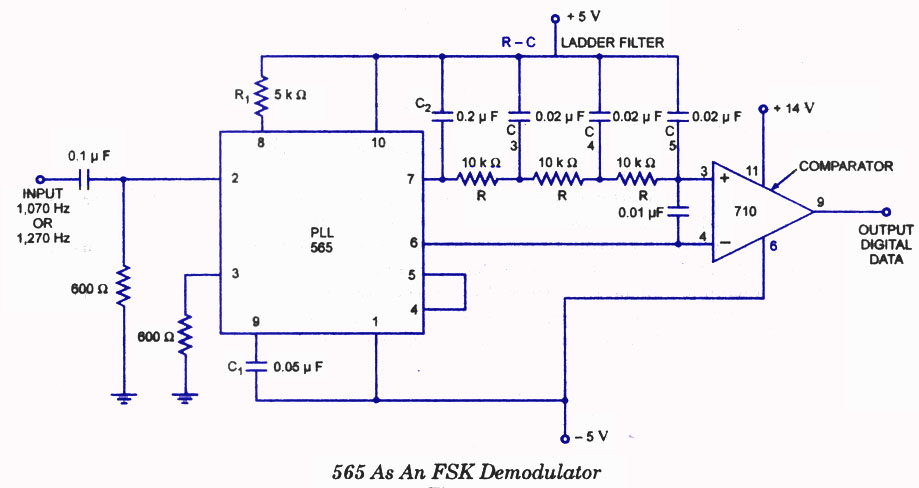
A highly effective application of the 565 Phase-Locked Loop (PLL) is its use as a Frequency Shift Keying (FSK) demodulator. In the 565 PLL, frequency shifting is typically achieved by driving a Voltage-Controlled Oscillator (VCO) with a binary data...
A Phase Locked Loop (PLL) can be utilized to create a Frequency Modulation (FM) demodulator. The PLL circuit tracks the input frequency by adjusting the voltage input of a Voltage-Controlled Oscillator (VCO). The Phase Locked Loop (PLL) is a critical...
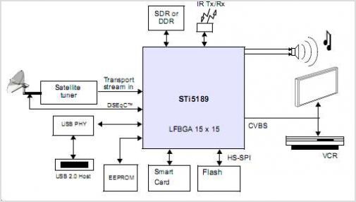
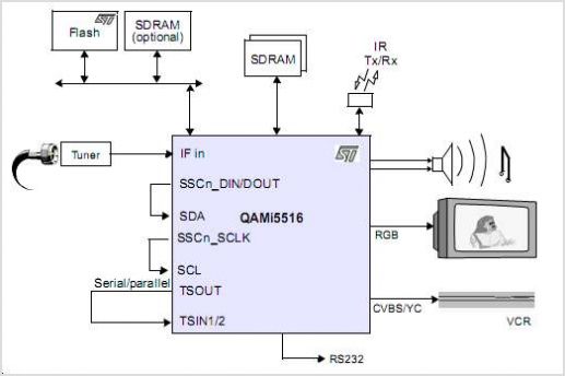
The STI5211 is a standard definition, full back-end processor designed for satellite set-top boxes, adhering to ATSC, SMPTE VC-1, DVB-S2, DIRECTV, DCII, and ARIB BS4 specifications. It delivers high performance for low-cost standard definition systems. Compared to the STi5202,...