
FM Linear Amplifier 400mW
The linear amplifier utilizing the 2N4427 transistors delivers substantial power to drive various linear amplifiers, including the BGY133 and other transistors like the BLY87. It operates within the UHF region, effectively amplifying signals from 70 MHz to 150 MHz, thereby covering the FM range. Although the gain decreases with increasing frequency, it remains stable in the FM region, providing 15 dB amplification across the 80 MHz to 110 MHz range. To eliminate harmonics from the amplifier output, a low-pass filter can be added to improve the response curve.
The VHF amplifier functions in Class A and is based on the well-known Philips transistor 2N4427, available in the TO39 package. The collector is connected to the metal housing, while the other terminals are not insulated. The 2N4427 transistor is known for its reliability, supporting higher currents and power compared to other transistors in its family.
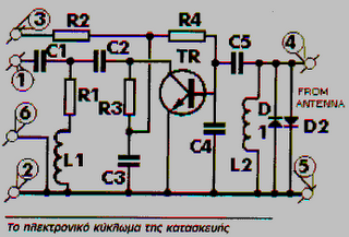
The theoretical circuit of the amplifier, while appearing simple, requires careful construction due to the high frequency range it operates within. It is recommended to assemble the circuit on a printed double-sided board using conventional materials, housed in a metal box for effective shielding and cooling.
The amplifier configuration provides approximately 10 dB gain per transistor, with the two transistors together achieving around 15 dB gain. A stabilized power supply with an output voltage of 12V and a current rating of 1A is recommended for optimal performance. The 2N4427 transistor is well-suited for output stages and finds applications in amplifiers, line-track systems, or transponder circuitry.
Transistors Q1 and Q2 are biased in Class A, with appropriate resistors ensuring the necessary biasing. Fixed capacitors are included in the base and collector circuits to match the input and output lines to 50 ohms. A low-pass filter is incorporated in the output without any variable capacitors.
Components:
Resistors:
- R1 = 4.7Ω
- R2 = 3.3KΩ
- R3 = 150Ω
- R4 = 270Ω
- R5 = 1.5KΩ
- R6 = 4.7Ω
- R7 = 100Ω
- R8 = 100Ω
- R9 = 470Ω
- R10 = 150Ω
Capacitors:
- C1 = 3.3nF
- C2 = 10nF
- C3 = 100pF
- C4 = 100pF
- C5 = 3.3nF
- C6 = 10nF
- C7 = 10nF
- C8 = 10nF
- C9 = 3.3nF
- C10 = 100pF
- C11 = 100pF
- C12 = 27pF
- C13 = 56pF
- C14 = 56pF
- C15 = 27pF
- C16 = 3.3nF
Other:
- Q1, Q2 = 2N4427
- L1, L2 = 1μH
The construction of the circuit is to be mounted on a compact, double-sided printed board. The assembly should be contained within a small metal box, measuring 10cm x 10cm. Input and output connectors are to be installed on opposite sides of the box, while a power supply connector should be placed on the remaining side. Optionally, a diode can be included in series with the circuit. The power supply should utilize capacitors connected in parallel, incorporating both ceramic and electrolytic types, with a recommended operating temperature of around 5°C.This amplifier is intended for amplifying low signals from oscillators in the FM band. It does not have frequency regulators with variable capacitors and coils, it has a wide range and moderate power capable of driving several linear amplifiers. The whole construction is based on the two low-power 2N4427 transistors, which are designed for the VHF range, and output up to 1W.
The amplifier is used in cases where additional amplification is required, such as after output of small transmitters. This is common, since many times to cover some bad conditions or big losses, we add an extra bandwidth amplifier, making it easier to drive long lines or lines with big losses, which is known to weaken the signal.
The linear amplifier with both 2N4427 offers powerful power to drive various linear ones such as BGY133 and various transistors such as BLY87. It works in the UHF region and can amplify signals from 70MHz to 150MHz, thus covering the FM range.
As the frequency increases, the aid decreases, but in practice we can see it as stable in the FM region.
The amplifier offers 15dB amplification across the range from 80MHz to 110MHz. If you want the amplifier output not to have harmonics, then you can add a low pass filter to correct the response curve.

Theoretical Circuit
The VHF amplifier works in Class A and is based on the well-known Philips transistor 2N4427, which is commercially available in the TO39 shell. Unlike the collector that is connected to the metal housing, the other terminals are not insulated.
The 2N4427 transistor has excellent reliability properties and features the best features of the rest of its family as it withstands higher currents and power.
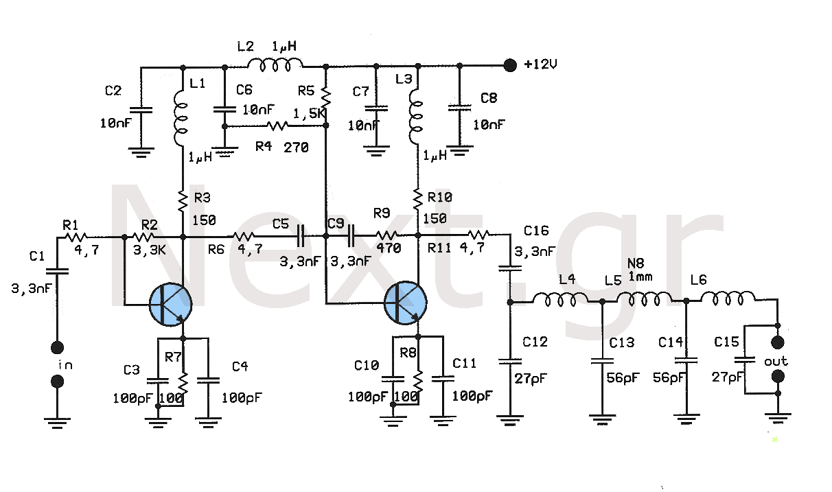
The theoretical circuit of the amplifier is shown in the figure.
Although the circuit of construction at first glance seems simple, we need to pay special attention during construction, since the high frequency range in which it works is quite difficult to handle.
The construction has to be implemented and assembled into a printed double-sided circuit with conventional materials. Use a metal box. The metal chassis ensures good operation, providing the necessary shielding and cooling.
The amplifier of the transistor is about 10dB, while the two transistors together amplify about 15dB.
The power supply voltage we recommend for the amplifier is a stabilized power supply with a very well stabilized output voltage of 12V and current 1A. The transistor 2N4427, manufactured by Philips, is a very good transistor for output stages and finds applications in amplifier, line-track or even transponder circuitry.
Transistors Q1 and Q2 are polarized in class A.
The necessary polarization is ensured by appropriate resistances. In the base and collector circuit there are fixed capacitors to adjust the input and output line to 50Ω. In the output there is a low pass filter, with no variable capacitors.

Components:
Resistors:
R1 = 4.7Ω, R2 = 3,3KΩ, R3 = 150Ω, R4 = 270Ω, R5 = 1,5KΩ, R6 = 4,7Ω, R7 = 100Ω, R8 = 100Ω, R9 = 470Ω, R10 = 150Ω
Capacitors:
C1 = 3,3nF, C2 = 10nF, C3 = 100pF, C4 = 100pF, C5 = 3,3nF, C6 = 10nF, C7 = 10nF, C8 = 10nF, C9 = 3,3nF, C10 = 100pF, C11 = 100pF, C12 = 27pF, C13 = 56pF, C14 = 56pF, C15 = 27pF, C16 = 3,3nF
Other:
Q1, Q2 = 2N4427
L1,L2 = 1μH
Construction
The construction of the circuit will be mounted on a small, double-sided printed.
The top view is shown in the figure, while in the next figure the bottom. The entire construction can be put into a small metal box. The dimensions of the box are 10cm x 10cm. On the opposite sides, you will insert the two input-output connectors. On the other side you will put a plug for the power supply voltage of the amplifier and if desired you can place a diode in series with the circuit. The power supply will be via capacitors connected in parallel with common ceramic and electrolytic capacitors.
The current of the power supply should be around 5°C.
Related Circuits
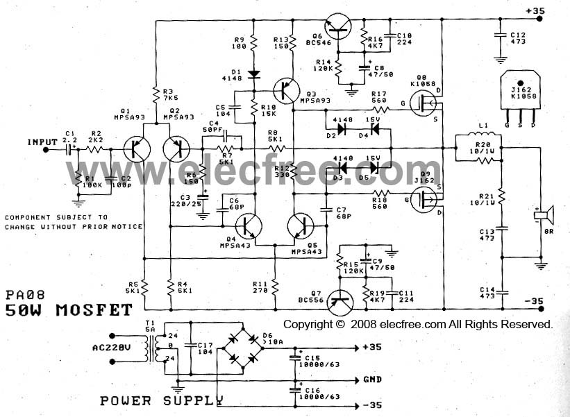
The 50W Power Amplifier OCL Mosfet (K1058 + J162) is simple to construct and cost-effective. It requires a power supply of +35V and -35V at 2A. The Power Mosfet used in this design is K1058 and J162. The 50W OCL...
The preamplifier in question is engineered to interface with various audio devices such as CD players, tuners, and tape recorders. Its primary function is to provide an alternating current (AC) voltage gain of 4, an attribute that allows it to...
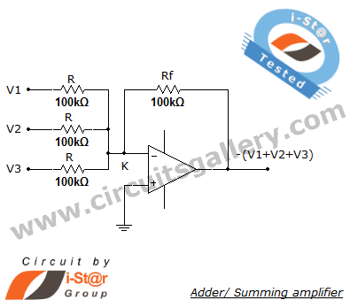
A summing amplifier, also known as an adder, is utilized to combine two or more signal voltages. This voltage adder circuit is straightforward and allows for the addition of multiple signals. It has a wide range of applications in...

The voltage Vc1 increases linearly when the pull-up resistor RA in the monostable circuit is replaced with a constant current source, resulting in the generation of a linear ramp. The figure illustrates the linear ramp generating circuit and the...
These frequencies include TV in VHF and UHF, as well as the radio broadcasting frequencies in the 88 - 108 MHz FM band. Component: Resistor, IC. The circuit described operates within the VHF (Very High Frequency) and UHF (Ultra High...
The 30-watt amplifier circuit provides a suitable power boost from an input of 4 watts up to 6 watts. It is designed to operate within the 88-108 MHz FM broadcast band and maintains stability while delivering a clean output...