
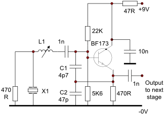
FM Modulator Circuit
The FM modulator circuit is designed for frequency modulation applications, utilizing the Motorola MC1648P as the primary oscillator component. This chip is known for its stability and ability to generate a reliable output frequency. The incorporation of two varactor diodes, specifically the MV-209, allows for effective frequency modulation by varying the capacitance and thus altering the frequency of the oscillator. The use of a 5000-ohm potentiometer provides a means to bias the varactors, ensuring the circuit operates within an optimal linearity range, which is crucial for achieving a clean and distortion-free output.
The output frequency of the modulator is centered around 100 MHz, with a tuning range of approximately ±10 MHz, allowing for flexibility in the transmission frequency. The output level is specified at -5 dBm, indicating a low power level suitable for short-range applications. The design also includes a coil and tuning diodes, which play a vital role in the tuning process. Alternatives to the MV-209, such as BB105 diodes, can be utilized, providing options for varying the circuit's performance characteristics.
Stability is enhanced by the MC1648 chip, which is regulated using a 5V zener diode. This regulation is essential for maintaining consistent performance, especially when powered by a 9V supply. However, it's important to acknowledge that without proper filtering, the circuit may produce unwanted harmonics, which can degrade the quality of the transmitted signal. Consequently, additional filtering components may be necessary to ensure compliance with transmission standards and to minimize interference with other devices.
The effective range of the FM modulator is limited, typically confined to a single room, making it suitable for personal use or small-scale applications. The output power, while low, can be amplified if necessary, allowing for broader transmission capabilities depending on the requirements of the application. Overall, this circuit serves as a foundational model for those interested in exploring FM modulation and radio frequency transmission.The FM modulator circuit (frequency modulation) is built with a Motorola MC1648P oscillator. Two varactors, Motorola MV-209 are used to frequency modulate the oscillator. The 5000 © potentiometer is used to bias the varactors for the best linearity. The output frequency of approximately 100 MHz can be adjusted by changing the value of the inducto r. The output frequency can vary as much 10 MHz on each side. The output level of the modulator is -5 dBm. In this fm modulator prototype the varactor bias was 7. 5V for the best linearity but this could be different with other varactors. Hi folks, for those of you who want to look at a good site, i suggest (ultimate site for learners and experienced alike. ) Dont send him silly questions though. From a one tranny circ. to more elaborate transmitters such as V7b and v7 As you can see above, there is a coil with two tuning diodes(mv209, 2 x bb105 or similar may work too) (find, the veronica 1 watt guys, similar tuning deal) the mc1648 chip is a stabiliser type chip regulated by the 5v zener, although you will find that this was quite a stable circuit without if the circuit ran off say a 9v regulator, the earliest model i can think of was a kids c.
b circuit and then the 3w pantek came from that (good sound, rubbish harmonics but stable). This is prone to harmonics with out the chip and a filter though. This will not propogate more than one room i would say. I see no amplification either. This should put out the few miliwatts that could be amplified. 🔗 External reference
Related Circuits

This emergency LED light is simple, inexpensive, and easy to build. The circuit connects to the battery, activating when the main power source is unavailable, such as during brownouts. White LEDs turn on automatically. Initially, the output voltage from...
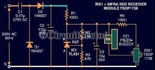
This document presents an infrared remote control tester circuit that can be constructed at a low cost. The circuit is built around the infrared receiver module TSOP1738. The state of the remote control can be observed through the sound...
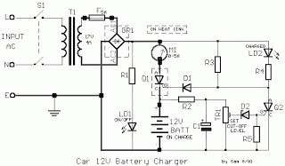
All car batteries require a 12V battery charger, which also applies to marine, RV, and power sports batteries. The high-efficiency lead-acid batteries available today necessitate more effective charging techniques. The battery charger is a crucial tool for prolonging battery...

There are two resonant circuits in a double-tuned amplifier circuit, which consists of transformers T1 and T2 with primary and secondary coils that include parallel resonance capacitors. This circuit exhibits a resonance function and can be classified based on...
This circuit operates effectively from low frequencies up to at least 120 MHz using series resonant crystals in their fundamental or overtone mode. The output can be obtained from the feedback tap, a low impedance winding on L2, or...
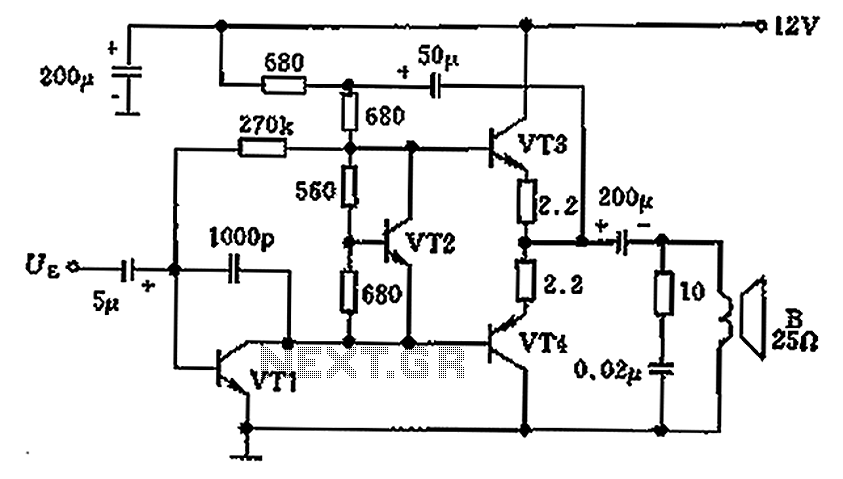
The overload protection circuit operates at a power of 650 mW with a supply voltage of 12 V and is designed for a speaker with an impedance of 25 ohms. The component specifications include: VT1 as transistor NB111EH/J, VT2...