
FM Moulator with IC 555

The FM modulator circuit employing the IC 555 is designed to facilitate the modulation of audio signals onto a carrier frequency, allowing the transmission of sound over radio frequencies. The core of the circuit consists of the IC 555 configured in astable mode, generating a square wave output that can be varied based on the input signal fed into pin 5. The frequency of oscillation is determined by the resistors and capacitor connected to the IC. The values of the resistors (6.8 kΩ and 3.3 kΩ) and the capacitor (0.1 µF) can be adjusted to produce different carrier frequencies, making the circuit versatile for various applications.
The absence of inductors simplifies the design, making it accessible for hobbyists and beginners in electronics. The circuit can be powered with a standard DC supply, typically ranging from 5V to 15V, depending on the specific requirements of the application. The output can be connected to an antenna for transmission, and the addition of an RF amplifier can help boost the signal strength for longer-range transmission.
In practical applications, this FM modulator can be employed in short-range wireless audio transmission, allowing audio signals from devices such as microphones or music players to be transmitted to FM receivers. The circuit's simplicity and effectiveness make it a suitable choice for educational projects and basic communication systems. However, for applications requiring higher fidelity, power, or frequency stability, more sophisticated modulation techniques and components may be necessary.FM Modulator circuit is a simple FM modulation circuit using IC 555, where the resulting modulated signal has a tenuous meeting depends on the signal frequency information. The resulting signal can be spelled out quite nice and stable so that the result will be more perfect.
No winding or inductor in series modulator, so you do not need to bother to make a winding and calculate the value of the coil that you created it. With this circuit the desired value of frequency modulation can be obtained easily by calculating the frequency of IC 555 in general, which is determined by the resistor 6. 8 K and 3. 3 K and 0. 1 UF capacitor. To obtain the other frequencies of your stay replace one or all three components. Actually fm modulator ic 555 circuit is very simple though, but I think it reliable enough to handle a simple application purposes that do not require a big power or a very high frequency.
But if you want more power you can add the RF amplifier circuit at the output of this circuit. Thus, the results of modulated signal can be amplified with the help of a series of supporters. In accordance with my experimental series modulators can work well at frequencies below the MHz range, because it is not IC IC 555 which is devoted to support of a very high frequency. You can use oscilltor transistor circuit, XTAL or others if you need a very high frequency. The difference circuit with IC 555 on the multivibrator circuit in general is the use of pin 5, on the FM Modulator circuit is pin 5 of IC 555 is used as input information signal, which in turn will influence the shape of the output signal (modulated).
But in applying this 5 pin multivibrator functions normally associated with 0. 01 UF capacitor or left alone. 🔗 External reference
Related Circuits

This is a simple water level alarm circuit made using a 555 timer IC. The circuit will produce an alarm when the water level reaches a preset level. The water level alarm circuit utilizing a 555 timer IC is designed...
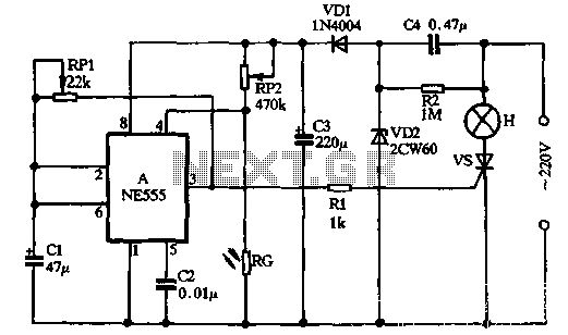
VDI, VD2, C3, and C4 form a simple half-wave rectifier capacitor step-down regulator circuit. This circuit can output approximately 12V DC voltage after power is applied across C3, which is utilized for the time base circuit. Additionally, the time...
is circuit was requested from an email. It will allow your car headlights to flash on and off at the same time or it will cause them to flash alternately. The circuit is based on the 555 timer. It...

The schematic presented originates from buildcircuit.com. This circuit functions as a music generator, infrared transmitter, and LED blinker, depending on the values of R1, R2, and C1. A minor modification to the previous circuit allows it to operate as...
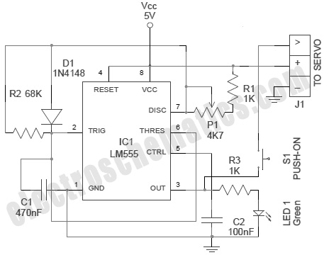
A servo is an error-sensing feedback control mechanism used to correct the performance of a system. A servo motor is a DC motor equipped with a servo mechanism. A servo motor is an electromechanical device that utilizes a closed-loop control...
The 555 Stepper Pulse Generator kit will help you with the pulse required to drive your favorite DC Servo Motor application. This kit uses the famous 555 timer IC for generating the Stepping Pulse. More: Input - 5 -...