
Wailing Alarm Siren

The wailing alarm circuit is designed to produce a loud sound when triggered, typically used in security systems or alert applications. The circuit operates by utilizing a combination of resistors and capacitors to create an oscillating signal that drives a piezoelectric buzzer or speaker.
The resistors R1, R2, R3, and R4 form a voltage divider and help set the operating point for the circuit. Resistor Rx, while not explicitly defined, would typically be used to adjust the sensitivity or frequency of the oscillation depending on the desired characteristics of the alarm. The values of the resistors are chosen to ensure that the circuit operates within a specific frequency range, which is crucial for generating the wailing sound.
Capacitors C1 and C4 are used for power supply filtering and stability, ensuring that the circuit receives a steady voltage. The electrolytic capacitors can handle higher currents and are essential for smoothing out any voltage fluctuations. Capacitors C2 and C3, with their smaller capacitance values, are likely used for timing purposes, helping to set the oscillation frequency of the circuit.
When the circuit is activated, the combination of these components allows for rapid charging and discharging of the capacitors, creating a square wave output that drives the alarm. The output can be connected to a loudspeaker or buzzer, producing the characteristic wailing sound that serves to alert individuals to a potential security breach or emergency situation. Proper layout and connection of these components are critical to ensure reliable operation and optimal performance of the alarm circuit.Here the wailing alarm circuit diagram: Component parts List: R1,R5 4.7KR2 47KR3 10KR4 100KRx *see text C1,C4 100uF/25V, electrolyticC2,C3 0.01uF (10nF),.. 🔗 External reference
Related Circuits
This simple alarm timer circuit is constructed using a 4060 integrated circuit, which features a stable oscillator with a relatively wide frequency range. The alarm timer circuit utilizes the CD4060 IC, which combines a low-frequency oscillator and a binary counter....
The circuit diagram of a police siren utilizes two NE555 timer integrated circuits (ICs), each configured as an astable multivibrator. It can operate with a power supply ranging from 6 to 15V DC and produces a loud sound. An...
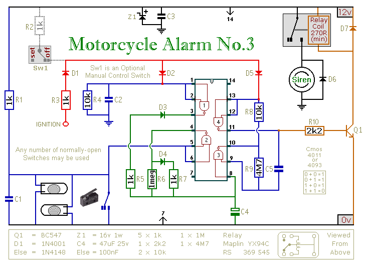
This circuit features an intermittent siren output and automatic reset. It can be operated manually using a key-switch or a hidden switch; but it can also be wired to set itself automatically when you turn-off the ignition. By adding...
An adaptable siren generator circuit with multiple applications is presented. It is based on a 556 twin-timer chip, IC1. One timer section generates an audio tone that is directly coupled to the driver transistor, TR1. The other half of...
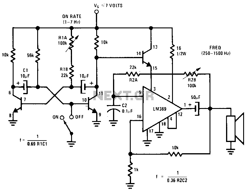
This circuit utilizes one of the LM389 transistors to control the power amplifier's operation by implementing a muting technique. The remaining transistors create a cross-coupled multivibrator circuit that regulates the frequency of the square-wave oscillator. The power amplifier functions...

The automatic door handle alarm circuit emits an audible alarm and activates an LED when someone touches the door handle. This latching circuit continues to produce sound until it is manually turned off. Transistor Q1 is configured as an...
Warning: include(partials/cookie-banner.php): Failed to open stream: Permission denied in /var/www/html/nextgr/view-circuit.php on line 713
Warning: include(): Failed opening 'partials/cookie-banner.php' for inclusion (include_path='.:/usr/share/php') in /var/www/html/nextgr/view-circuit.php on line 713