
HiFi preamplifier for computer soundcard circuit
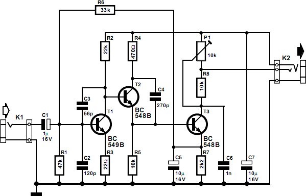
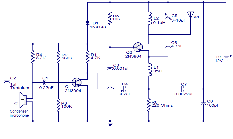
This preamplifier circuit is essential for integrating inductive pick-up elements and dynamic microphones with modern soundcards, which typically offer limited compatibility with these types of microphones. The design leverages discrete transistors to achieve a high level of amplification and stability, making it suitable for a variety of audio applications. The use of capacitors for decoupling and filtering ensures that the signal remains clean and free from unwanted noise, while the feedback mechanisms employed throughout the circuit enhance performance by ensuring stability and minimizing distortion. Such a design is particularly advantageous in environments where audio fidelity is paramount, allowing for the capture of high-quality sound without the drawbacks often associated with lower-quality integrated circuits. The careful selection of components and their arrangement within the circuit further optimize the preamplifier's performance, making it an effective solution for users seeking to utilize traditional audio equipment in conjunction with contemporary digital systems.This circuit can be used for inductive pick-up elements and dynamic microphones Most soundcards have a line` input and one for an electret (condenser) microphone. To be able to connect an inductive tape-recorder head or a dynamic microphone, an add-on preamplifier is needed.
Even in this day and age of integrated microelectronics, a transistorised circuit built from discrete part has a right of existence. The preamplifier described in this short article goes to show that it will be some time before discrete transistors are part of the silicon heritage. The preamplifier is suitable for use with a soundcard or the microphone input of a modem. As you will probably know, most sound-cards have input sockets for signals at line level (stereo), as well as one for a (mono) electret microphone.
For the applications we have in mind, connecting-up an inductive pick-up element or a dynamic microphone, both inputs are in principle suitable, provided the source signal is amplified as required. The author eventually chose the microphone input on the soundcard. Firstly, because the line inputs are usually occupied, and secondly, because the bias voltage supplied by the micro-phone input eliminates a separate power supply for the preamplifier.
The microphone input of a soundcard will typically consist of a 3. 5-mm jack socket in stereo version, although only one channel is available. The free contact is used by the soundcard to supply a bias voltage to the mono electret microphone. This voltage is accepted with thanks by the present preamplifier, and conveniently obviates an external (mains adaptor) power supply. In true transistor-design fashion, the preamplifier consists of three stages. Capacitor C1 decouples the signal received from the microphone or pick-up element, and feeds it to the input of the first stage, a transistor in emitter configuration, biased to provide a current amplification of about 300 times.
Together with the source impedance of the microphone or pick-up element, capacitors C2 and C3 form a low-pass filter which lightly reduces the bandwidth. In addition, the output low-pass, R2-C3, reduces the dynamic collector resistance at higher frequencies.
In this way, the filter reduces the gain in the higher part of the frequency spectrum and so helps to eliminate any oscillation tendencies. The first, high-gain, stage is terminated by T2. Unlike T1, this transistor does not add to the overall gain, because the output signal is taken from the emitter (common-collector circuit).
T2 thus acts as an impedance converter, with C4 reducing any tendency to oscillation. The output stage around T3 is a common-emitter circuit again. In it, preset P1 determines the voltage amplification. T3 is biased by means of a direct-current feedback circuit based on components R7 and C5. To this is added an overruling` dc feedback path back to the input transistor, via R6. This measure guarantees good dc stability in the preamplifier. The circuit is small enough to be built on a piece of veroboard or stripboard, and yet remain reasonably compact. To prevent interference from external sources, the completed board should be mounted in a properly screened (metal) enclosure, with the connections to the input source and the sound card made in screened cable.
The preamplifier provides a frequency-linear response. In case the source signal is marked by frequency correction (e. g. , RIAA), then a matching linearization circuit should be used if the relevant signals are used by the computer. 🔗 External reference
Related Circuits
The circuit contributes 3.2 nV/√Hz of voltage noise and 0.45 pA/√Hz of current noise. To minimize noise from other sources, resistor R3 is configured to 100 ohms, resulting in an additional voltage noise of only 1.3 nV/√Hz. Resistors R1,...
This is a single-channel (on/off) universal switch that can be used with any infrared remote control operating within wavelengths of 850-950 nm. The single-channel universal switch functions as a simple on/off control mechanism, allowing users to operate electronic devices remotely...
The Delta configuration of resistors R2, R3, and R4 is converted to a Wye (Y) configuration. This conversion is necessary because a voltage divider is typically employed in series circuits. The aim is to determine the total resistance in...
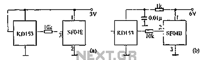
The circuit diagram illustrates the SF04E emission and the corresponding SF04B. Part (A) depicts the composition of the remote control transmitter SF04E, along with its compatible receiving circuit, which can be assembled using the SJ04H. Part (B) presents the...
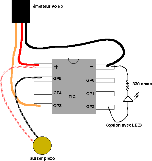
For the simplest functions, such as a flashing indicator and/or beeper, a printed circuit board is not necessary. Components can be directly soldered onto the legs of the PIC microcontroller, using heat-shrinkable sleeves for insulation. Caution is advised to...
The FM transmitter circuit presented is both stable and simple. With an adaptive antenna, it can achieve a transmission range of approximately 200 meters. This transmitter was developed this year and has yielded positive results. The circuit operates using...