
fm radio receiver circuit with ic tda
The TDA 7012T FM radio receiver IC is engineered to provide robust performance in compact electronic designs. Its architecture enables efficient FM signal processing, making it suitable for personal audio devices, portable radios, and other consumer electronics. The IC integrates key functionalities, such as demodulation and audio processing, into a single package, thereby reducing the overall component count and simplifying the design process.
To implement the TDA 7012T in a circuit, a few essential external components are required. These typically include an antenna for signal reception, capacitors for filtering, and resistors for biasing and impedance matching. The RC filter plays a critical role in enhancing the selectivity of the receiver, allowing it to distinguish between closely spaced frequencies and minimizing interference from adjacent channels.
The operational frequency range of the TDA 7012T is optimized for standard FM broadcast bands, making it versatile for global applications. A key feature of the IC is its ability to operate at low voltage, which is beneficial for battery-powered devices, ensuring longer operational life without compromising performance.
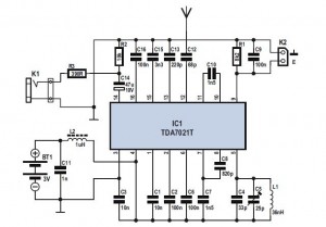
In summary, the TDA 7012T FM radio receiver IC is a highly efficient and compact solution for FM reception, characterized by its user-friendly design and minimal external component requirements. Its integration of advanced features, such as the Frequency Locked Loop and enhanced selectivity through RC filtering, makes it an ideal choice for modern electronic applications.FM Radio Receiver IC TDA 7012T is very simple, but it has an FM radio receiver sensitivity and good selectivity. Single Chip FM Receifer cool name of IC TDA7012T 7012T TDA is to build an FM receiver requires a few additional components.
Feature contained in FM receiver IC TDA 7012T is quite tempting to an FM receiver. Among features an FM receiver TDA 7012T is a low-voltage applications micro affability arrangement (MTS), Frequency Loked Loop (FLL) to 76 KHz range and selectivity of FM receiver with RC Filter. In an article by FM Radio Receiver IC TDA 7012T can be seen in the FM receiver circuit which can be made.
🔗 External reference
Related Circuits
Writing about multiple circuits in Marx, an entire new set has been discovered, referred to as "the" Marx Generator. There are diagrams available, along with a useful quote: "The main advantage of the Marx circuit configuration over a more...
This custom mod gives your computer the personality of KITT, the computerized car from Knight Rider TV fame. The project is a light display which imitates the dot in KITT's hood. It looks like the scanning eye of the...
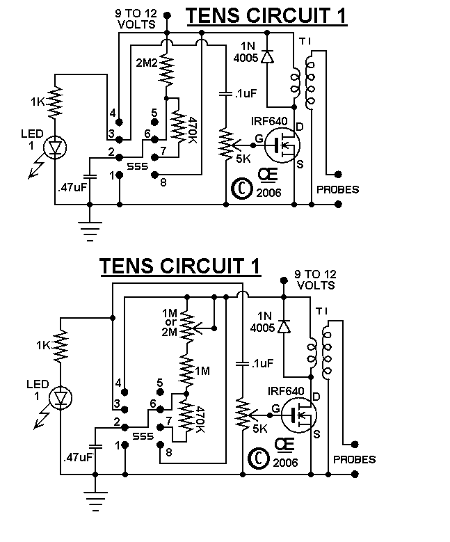
The circuits were originally designed for an individual with muscle issues. Although they were reported to function effectively, the use of these devices is not recommended for anyone, and no responsibility or liability is accepted for their assembly or...
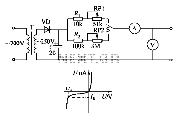
To ensure proper operation of the transistor in a circuit, it is essential to measure the reverse breakdown voltage of the transistor. This is particularly important for tubes with high reverse breakdown voltage requirements, such as those used in...
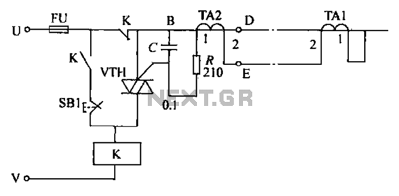
The circuit's current exceeds the load carried by the rated current meter, prompting the user to immediately cut off the power supply to address the overload. Pressing the reset button restores power, making the system simple, convenient, and practical....
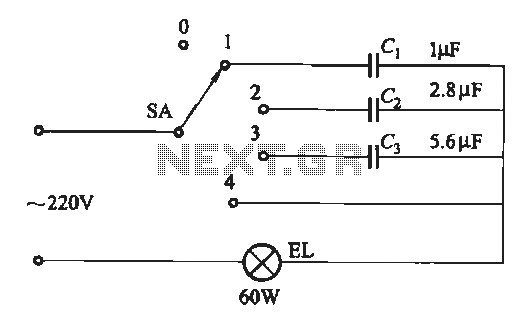
A dimming circuit capacitor circuit is illustrated in Figure 2-63. When the switch SA is moved from position "1" to "3," the capacitance increases in ascending order, resulting in the light bulb brightness also increasing correspondingly. When SA is...