
FM Radio with TDA7000
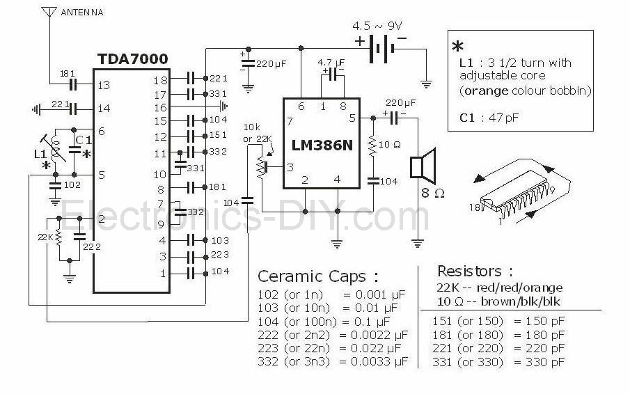
The FM radio circuit based on the TDA7000 and LM386 offers a robust solution for receiving FM signals with minimal components. The TDA7000 chip's architecture allows for a simplified design without sacrificing performance. The single-tuned circuit configuration minimizes complexity while maintaining effective reception capabilities. The low intermediate frequency of 70 kHz is a strategic choice, enabling the use of standard op-amp circuits for amplification and filtering, which can be advantageous for designers looking to reduce component count and cost.
The Frequency Locked Loop (FLL) mechanism is a critical feature of this radio design, ensuring that the local oscillator dynamically adjusts to the incoming signal's frequency variations. This adaptability is essential for maintaining sound clarity and reducing distortion. The bandwidth limitation provided by the FLL allows the circuit to handle the inherent characteristics of FM broadcasting effectively, ensuring that the output remains within acceptable limits for audio fidelity.
The inclusion of a noise generator in the squelch circuit is particularly noteworthy, as it enhances user experience by providing audio feedback even when no station is being received. This feature can be particularly useful in environments where silence may be disconcerting. For users who prefer a more traditional approach, the ability to disable this feature through simple modifications illustrates the flexibility of the design.
Overall, the integration of the TDA7000 and LM386 in this FM radio project exemplifies modern design principles in electronics, focusing on efficiency, performance, and user-centric features. The circuit can serve as a valuable reference for engineers and hobbyists interested in radio frequency applications, providing insights into the practical implementation of integrated circuits in communication systems.This project is a FM Radio based on TDA7000 and LM386 integrated circuits. What is unusual about TDA7000 IC is how it operates. It is a proper FM superhet receiver, with the usual local oscillator, mixer, IF amplifier, limiter, and phase detector. The difference is that there`s only one tuned circuit; the local oscillator. Like the Pulse Counting Receiver, the TDA7000 relies on a low IF so that ordinary Op Amp circuitry can take care of the gain and bandpass characteristics.
Only 70Kc/s is used with the TDA7000. Now, you might remember that the deviation of a broadcast FM signal is +/- 75Kc/s. A fully modulated signal would therefore sound rather distorted. So, how can this IC work? It`s quite simple in that there is what Philips call a Frequency Locked Loop. Basically, the local oscillator is shifted in response to detector output so that the bandwidth of the mixer output is never more than +/- 15Kc/s. It is actually compressing the frequency range of the modulated signal. The muting or squelch feature is novel to say the least. Although it performs as any other muting circuit does, the TDA7000 provides an artificial noise generator so that the receiver still sounds alive while tuned off station.
If you don`t need that feature, just remove the .022uF condenser at pin 3. Not all Philips data sheets show it, but connecting a 10K resistor from the supply to pin 1 will disable the squelch. 🔗 External reference
Related Circuits
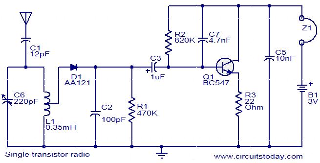
The circuit diagram represents a simple radio utilizing one transistor and several passive components. The components C6 and L1 form a tank circuit that captures signals from the desired radio station. The diode D1, capacitor C2, and resistor R1...
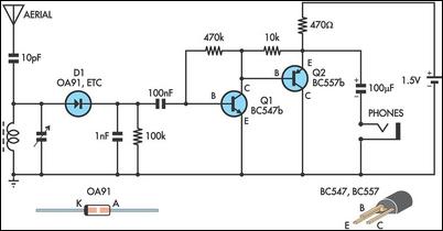
This circuit is essentially an amplified crystal set. The inductor could be a standard AM radio ferrite rod antenna while the tuning capacitor is a variable one. The described circuit operates as an amplified crystal radio receiver, which utilizes a...
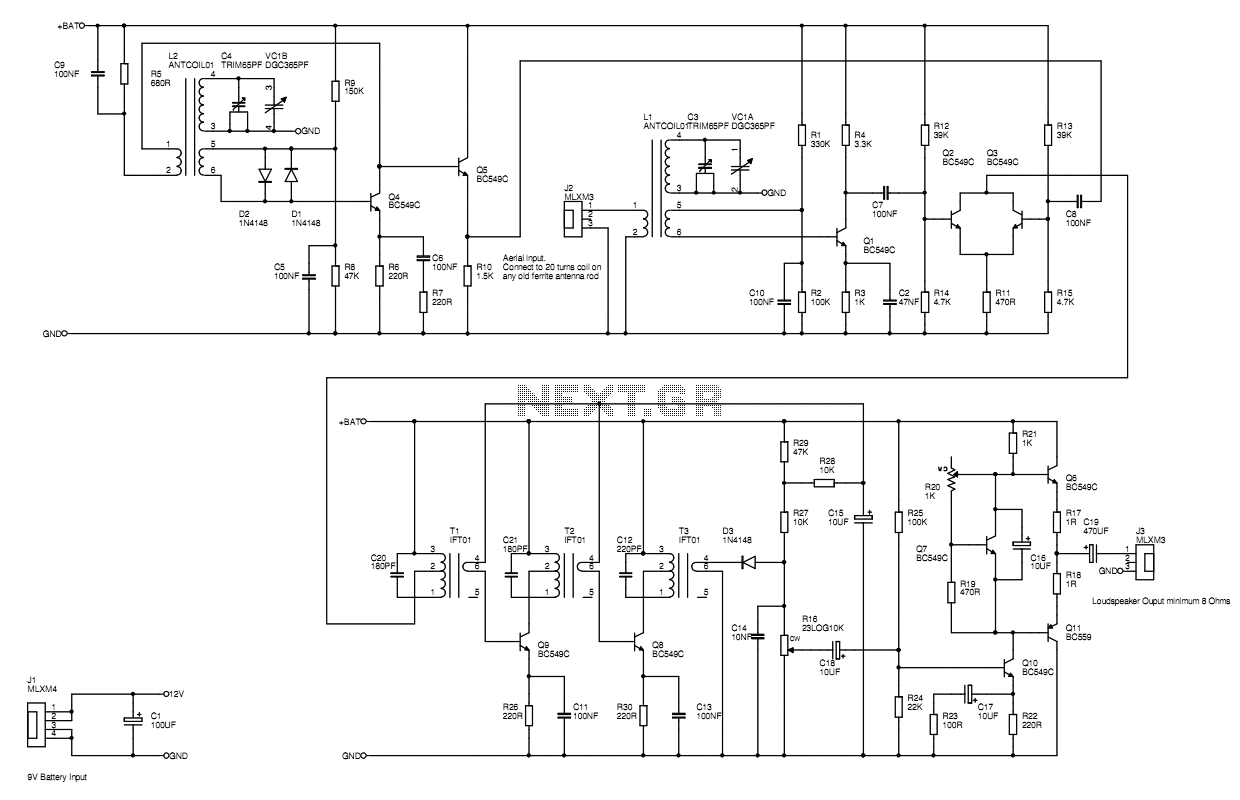
A MW AM radio like those you buy, or used to buy. Use just BC549 trannies, with the BC559 complement being allowed in the audio output stage. Buying RF antenna coils, oscillator coils and intermediate frequency transformers would be...
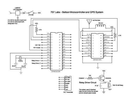
The balloon reached a peak altitude of 103,258 feet. Several factors needed to be considered when launching a payload to this height. Unlike creating an electronics package for sea level, variables such as air pressure, temperature, relative humidity, and...
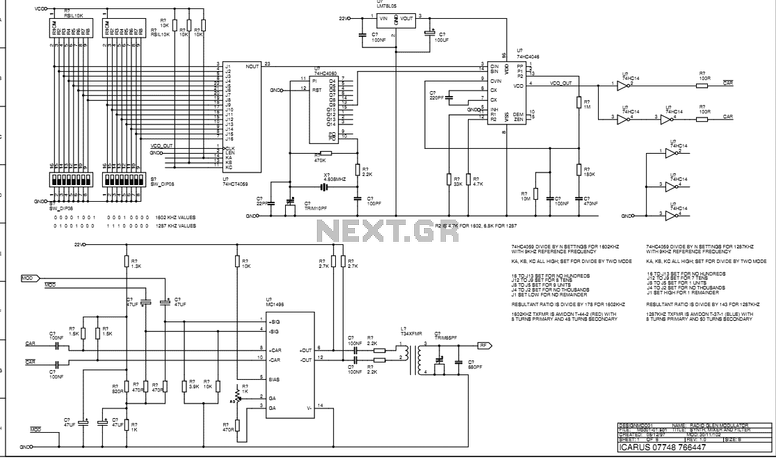
This document describes the transmitter system supplied to Radio Glen for testing as designed and constructed by Henry. The transmitter is supplied in prototype form and has the physical limitations of an instrument constructed using prototyping techniques. The transmitter...
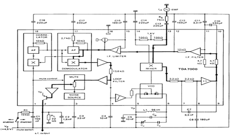
The TDA7000 is an integrated circuit (IC) designed for FM portable radios, featuring a Frequency-Locked Loop (FLL) system with an intermediate frequency of 70 kHz. It incorporates several functions, including an RF input stage, mixer, local oscillator, IF demodulator,...