
Single transistor radio
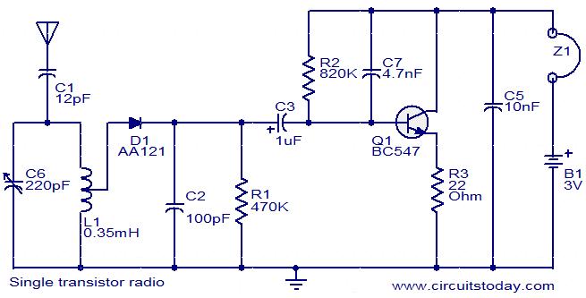
The described circuit operates as a basic AM radio receiver, utilizing a single transistor (Q1) to amplify the audio signal. The tank circuit formed by capacitor C6 and inductor L1 is crucial for tuning into specific frequencies, allowing the circuit to select and amplify the desired radio station's signal. The tank circuit's resonant frequency is determined by the values of C6 and L1, and it can be adjusted to receive different stations by varying these components.
The detection stage, which involves diode D1, capacitor C2, and resistor R1, plays a critical role in demodulating the amplitude-modulated signal. The diode rectifies the incoming radio frequency (RF) signal, allowing only the positive half-cycles to pass through. Capacitor C2 smooths out the rectified signal, while resistor R1 helps to set the appropriate load for the detection process, ensuring that the audio signal is cleanly extracted.
Once the signal is detected, capacitor C3 couples the audio signal to the base of Q1. This coupling is essential as it allows the amplified audio signal to be transmitted without affecting the biasing of the transistor. The biasing of Q1 is managed by resistor R2, which ensures that the transistor operates in its active region, providing the necessary gain for the audio signal.
The collector current of Q1 is limited by resistor R3, which protects the transistor from excessive current that could lead to overheating or damage. The output audio signal is taken from the collector of Q1, where it can be connected to high-impedance headphones. The design's simplicity and reliance on a minimal number of components make it an excellent project for beginners in electronics, demonstrating fundamental principles of radio frequency reception and amplification. The circuit's effectiveness is contingent upon the presence of sufficient radio signal strength in the operating environment.Here is the circuit diagram of a simple radio that uses one transistor and few other passive components. The C6 and L1 forms a tank circuit which picks up the signal from your desired radio station. Diode D1, capacitor C2 and resistor R1 does the detection of the picked signal. The detected signal is coupled to the base of Q1 through capacitor C3. The Q1 gives required amplification to the signal. The resistor R2 is used to bias Q1. R3 limits the collector current of Q1. The audio output will be available at the collector of Q1 and it can be heard by using a high impedance head phone. This radio will work only at places where there is reasonable radio signal strength. 🔗 External reference
Related Circuits
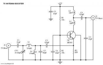
This is a straightforward circuit for a UHF band TV antenna booster that provides a gain of 15 dB. This low-cost antenna booster is simple and easy to construct. The UHF band TV antenna booster circuit is designed to enhance...

This design circuit functions to filter out interference signals, ensuring that the signal received from a Morse code station is distinct. The circuit utilizes the earliest mode of radio communications, which employs Morse Code on a continuous wave carrier...
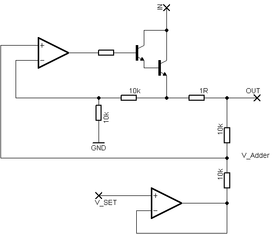
Rsense will cause Q2 to conduct when a threshold of approximately 0.65V is reached. Rbias will determine the extent of this limitation, although this aspect remains unclear. Particularly, if Rsense is positioned on the high side, simply activating Q2...
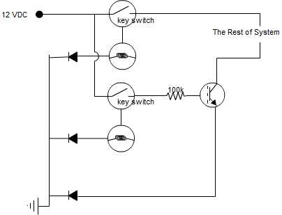
A circuit is being designed that incorporates two key switches, which must both be closed for current to flow through the circuit. The proposed circuit configuration employs two key switches connected in series. In this arrangement, the current can only...
2012 Honda Odyssey Radio Wiring Diagram Manual PDF Download. The 2012 Honda Odyssey Radio Wiring Diagram Manual provides a detailed schematic of the audio system's wiring configuration for the vehicle. This manual is essential for understanding the connections and functionalities...
Construct a basic audio amplifier utilizing transistors. While integrated circuit (IC) designs are available for this purpose, the intention is to use transistors to gain practical knowledge about their amplification capabilities. The article "Amplifier Basics - How Amps Work...