
Transistor Ignition

The transistor ignition circuit is designed to optimize the ignition timing and improve the overall performance of an internal combustion engine. It employs a transistor-based switching mechanism that replaces traditional mechanical points, leading to more precise control over the ignition process. This increased precision allows for better combustion efficiency, which results in enhanced power output and smoother engine operation across a wider range of RPMs.
Key components of the circuit typically include a power transistor, a resistor, a capacitor, and a series of diodes. The power transistor acts as a switch that controls the flow of current to the ignition coil. When the ignition key is turned, the circuit is energized, allowing the capacitor to charge through the resistor. Once the voltage across the capacitor reaches a certain threshold, the power transistor switches on, delivering a high-voltage pulse to the ignition coil. This pulse generates a spark at the spark plugs, igniting the air-fuel mixture in the combustion chamber.
The use of a transistor instead of mechanical points eliminates issues such as point bounce and wear, resulting in increased reliability and reduced maintenance. Additionally, the circuit can be designed to include features such as adjustable timing and dwell control, allowing for further optimization based on specific engine characteristics.
Overall, this transistor ignition circuit not only improves the operational efficiency of the vehicle but also supports environmental sustainability by reducing harmful emissions. As a result, it is a valuable upgrade for enhancing vehicle performance and longevity while promoting economical driving practices.This transistor ignition circuit give your car to have better starting and smoother running, particularly at very high and very low RPM. Lower fuel consumption, less pollution, lower servicing costs. Drive economically, drive electronically.. 🔗 External reference
Related Circuits
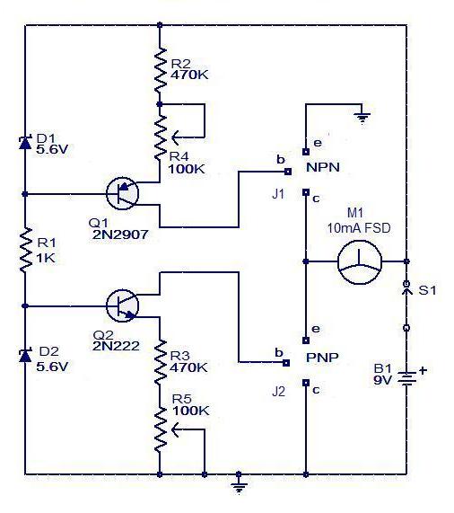
The circuit for a transistor tester is a relatively simple device. The transistor tester circuit illustrated below can be utilized to measure and identify the pins of a transistor, as well as determine its condition. Furthermore, this circuit can...
This small transmitter can reach distances of more than 1 km under favorable transmission conditions. Modulation can be achieved using a microphone, such as an electret microphone, or another audio source. The transmitter includes a coil made of 5...
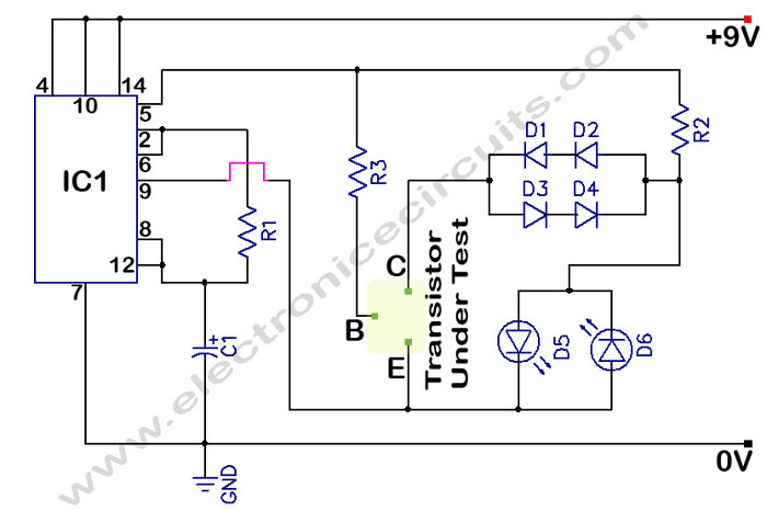
The circuit is a transistor tester schematic that indicates the condition of a transistor using two LEDs. It is designed to test a good NPN transistor. The transistor tester circuit operates by utilizing two light-emitting diodes (LEDs) to provide a...
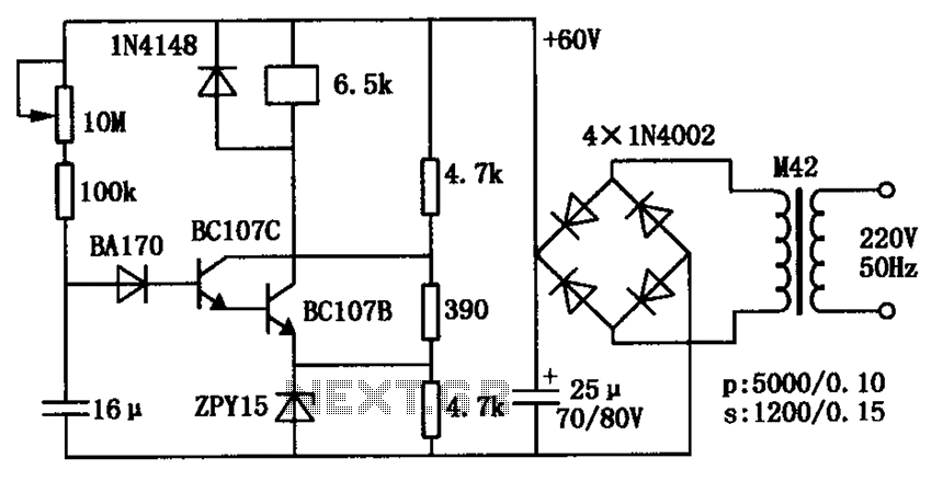
The circuit consists of a transistor relay delay pull mechanism. Initially, with a 16 µF capacitor at zero voltage, both transistors are off, and the relay remains inactive. As the 16 µF capacitor charges over time, the voltage increases...
This article describes a band-pass filter circuit diagram utilizing transistors. A band-pass filter is an essential electronic circuit that allows signals within a certain frequency range to pass while attenuating frequencies outside that range. The circuit typically consists of a...
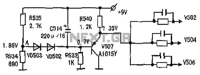
The common-emitter amplifier circuit V502, V504, V506 is designed to generate a static potential bias voltage through an emitter follower configuration, as illustrated in Figure 3. The active filter is formed by components V507, VD502, and VD503. The emitter...