
FM transmitter with two 2N3904

The circuit described functions as a basic FM transmitter, utilizing a small microphone for audio input and transistors for amplification and modulation. The initial stage consists of a microphone, which converts sound waves into electrical signals. This signal is then processed through a series of resistors that help set the correct biasing conditions for the microphone, ensuring optimal performance.
Following the microphone, a capacitor is employed in conjunction with the first transistor to amplify the audio signal. The transistor operates in the active region, where it increases the amplitude of the input signal, making it suitable for further processing. The amplified audio is then fed into the next stage of the circuit, which is responsible for generating the radio frequency (RF) signal.
The RF generation stage typically includes a second transistor, a coil, and additional capacitors. The coil, consisting of approximately nine turns of wire, is wound around a cylindrical object, such as a pencil, to maintain a consistent diameter. This coil acts as an inductor, which, in combination with the capacitors, forms a tank circuit that determines the oscillation frequency of the RF signal.
A trimmer capacitor, identifiable by its adjustable screw, is integrated into this stage to allow fine-tuning of the transmission frequency. By adjusting this capacitor, the user can select a specific frequency or station for the transmitter to operate on, ensuring compatibility with standard FM receivers, such as car stereos.
The final output of the circuit is a modulated RF signal that combines the amplified audio from the microphone with the carrier wave generated by the tank circuit. This modulated signal is then transmitted through an antenna, allowing it to be picked up by nearby FM receivers. Overall, this circuit exemplifies a straightforward approach to audio transmission using basic electronic components, making it an educational project for those interested in radio frequency communication.This circuit uses a small microphone to capture the sound and some transistors to generate radio waves that can be picked up by a FM receiver like a car stereo. The first part is the microphone and some resistors to get it working. Next we have a capacitor and the first transistor, this amplifies the sound from the microphone so that it can be loud enough to work with.
The last part, there is a transistor, a coil and some capacitors. This part generates the radio waves and combines them with the sound from the mic to transmit it thru the antenna. The coil is made with about 9 turns of wire, use a pencil to get the right diameter for the coil. The capacitor with the arrow is called a trimmer capacitor, it has a small screw to adjust the value, we'll use it to tune a certain frequency or station to transmit on. 🔗 External reference
Related Circuits
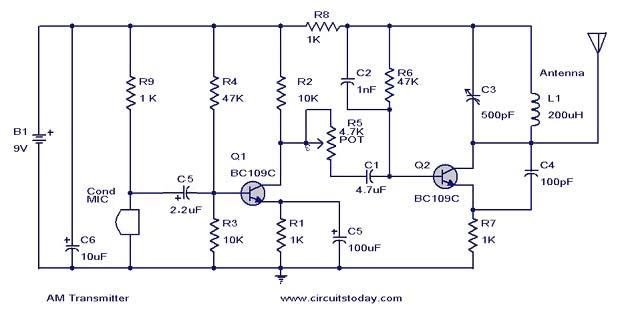
This document presents a circuit diagram of a simple AM transmitter that is capable of transmitting audio signals to a specified area. The circuit is designed with a limited power output to comply with FCC regulations while effectively producing...
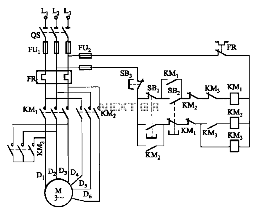
The circuit depicted in Figure 3-96 features a low-speed operation button (SBz), a high-speed operation button (SBi), and a stop button (SB3). In this configuration, a motor is connected in such a way that when the low-speed button is...
The circuit was designed to produce a 500mW output power transmitter whose signal is modulated by FM using four transistors. This circuit functions as a frequency modulation (FM) transmitter, capable of delivering an output power of 500 mW. The...
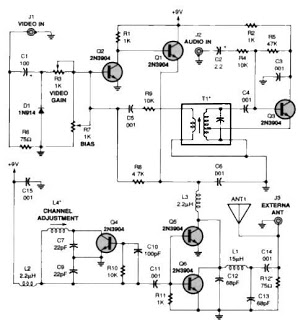
A simple TV audio-video transmitter circuit can be constructed using this schematic diagram. This circuit allows for the transmission of video signals from a VCR or other devices to a TV without the need for cables. The video signals...
To achieve a low-cost, accurate, and simple position control system, a stepper motor can be utilized. A circuit designed to drive the motor should be mounted in proximity to the motor itself. Stepper motors are widely employed in applications requiring...
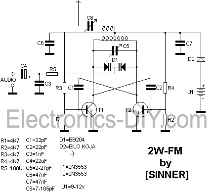
This 2 Watt FM transmitter is capable of providing a range of up to 10 kilometers under optimal weather conditions. For maximum range, a dipole antenna should be utilized. The transmitter can be tuned to frequencies between 88 and...