
Ultra-Simple Microphone Preamplifier

This microphone preamplifier circuit is designed to be user-friendly and adaptable for various audio applications. The double-sided PCB layout, while typically more complex, is made accessible through the straightforward design, which minimizes the likelihood of user error during assembly or modification. The choice of the NE5532 op-amp is significant due to its low noise characteristics and high performance, making it suitable for professional audio applications.
The gain configuration allows for flexibility based on user needs, with the option to adjust resistor R6 for those requiring a different gain structure. However, the preamp is optimized for a gain range that should suffice for most standard applications. The design's robustness is further enhanced by the use of high-quality components, including metal film resistors that contribute to the overall performance and reliability of the circuit.
The input capacitors are vital for defining the low-frequency response of the preamp. Users who require extended low-frequency performance can easily modify the capacitor values, demonstrating the design's adaptability. The physical dimensions of the PCB facilitate easy integration into various enclosures, while the mounting options for the XLR connector ensure compatibility with different setups.
Overall, this microphone preamp circuit serves as an effective solution for users needing a reliable and straightforward interface for balanced microphones, making it a valuable addition to any audio project.This little project came about as a result of a design job for a client. One of the items needed was a mic preamp, and the project didn`t warrant a design such as the P66 preamp, since it is intended for basic PA only. Since mic preamps are needed by people for all manner of projects, this little board may be just what`s needed for interfacing a b
alanced microphone with PC sound cards or other gear. Unlike most of my boards, this one is double-sided. I normally avoid double-sided PCBs for projects because rework by those inexperienced in working with them will almost certainly damage the board beyond repair. I consider this not to be an issue with this preamp, because it is so simple. It is extremely difficult to make a mistake because of the simplicity. As you can see, the board uses a PCB mounted XLR connector and pot, so is a complete mic preamp, ready to go.
Feel free to ignore the terminals marked SW1 (centred between the two electrolytic supply caps), as they are specific to my client`s needs and are not useful for most applications. The original use was to use them for a push-button switch that activated an audio switch via a PIC micro-controller.
They are not shown on the schematic. The DC, GND and output terminals may be hard wired to the board, you may use PCB pins or a 10-way IDC (Insulation Displacement Connector) and ribbon cable. Power can be anything between +/-9V and +/-18V with an NE5532 opamp. The mic input is electronically balanced, and noise is quite low if you use the suggested opamp. Gain range is from about 12dB to 37dB as shown. It can be increased by reducing the value of R6, but this should not be necessary. Because anti-log pots are not available, the gain control is not especially linear, but unfortunately in this respect there is almost no alternative and the same problem occurs with all mic preamps using a similar variable gain control system.
The circuit is quite conventional, and if 1% metal film resistors are used throughout it will have at least 40dB of common mode rejection with worst-case values. The input capacitors give a low frequency rolloff of -3dB at about 104Hz. If better low frequency response is required, these caps may be increased to 4. 7uF or 10uF bipolar electrolytics. These will give response to well below 10Hz if you think you`ll ever need to go that low. The project PCB measures 77 x 24mm, and the mounting centers for the pot and XLR connector are spaced at 57mm.
If preferred, a traditional chassis mounted female XLR can be used, and wired to the board with heavy tinned copper wire. The PCB pads for the connector are in the correct order for a female chassis mount socket mounted with the "Push" tab at the top.
🔗 External reference
Related Circuits
An RF condenser design powered by 12V was supplied to the microphone through the microphone cable using a phantom circuit. This marks the first known application of a phantom circuit for microphone powering. Around 1970, Neumann introduced the Fet-80...
The interest in tube circuits remains significant. Therefore, I will provide a comprehensive circuit of a preamplifier that is sufficiently detailed. It is primarily composed of the main preamplifier department, the input selector department, application voltage delay, and the connection...
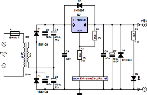
48 V phantom powering has become the standard for professional condenser microphones. The supply voltage is applied over both wires of the balanced screened cable via two 6.8 kΩ resistors. The absolute value is not critical, as a variation...
The circuit was designed to create a modular Class A buffer preamplifier to isolate stages in an audio circuit. BF245 is a general-purpose N-Channel JFET used in this design. The modular Class A buffer preamplifier serves as an essential component...
The circuit design utilizes a VHF amplifier configured to operate within the frequency range of 88 to 108 MHz, specifically for Band 2 radio applications. The VHF amplifier circuit is designed to enhance weak radio frequency signals in the specified...
The Audio Research Corporation LS22 Line Stage Preamplifier was selected for this upgrade. The Audio Research LS22 Line Stage Preamplifier is a high-performance audio component designed to enhance the quality of sound reproduction in audio systems. This preamplifier features a...