
Four channel RF remote control

This RF transmitter circuit is designed for straightforward implementation in remote control applications. The Holtek HT-12E encoder chip serves as the core component for encoding data, while the AM 418MHz transmitter module facilitates wireless transmission. The flexibility in power supply voltage allows for versatile usage across various applications, and the low current consumption ensures energy efficiency.
The oscillator resistor R1 plays a crucial role in determining the operating frequency of the system. The oscillator frequency recommendations provided in the datasheet assist in achieving optimal performance. The operation begins when any of the switches S1 to S4 is activated, which triggers the /TE pin. This action powers the encoder and transmitter, initiating the serial transmission of the address and data.
The receiver circuit, utilizing the HT-12D decoder chip, is responsible for interpreting the received signals. The continuous comparison of received data with local addresses ensures reliable communication. Upon successful matching, the data is decoded and made available at the output pins, which can then control various load devices through the TIP30 PNP transistors.
The design emphasizes the importance of antenna placement for maximizing transmission range. It is recommended to select antennas that are compatible with the frequency of operation and to position them away from metallic objects to minimize interference and signal degradation. Overall, this RF transmitter and receiver circuit provides a robust solution for wireless control applications.This is a very simple RF transmitter circuit that consists of the Holtek HT-12E encoder chip and AM 418MHZ-transmitter module ( WZ-X01 ). Using the hybrid RF xmit/receive modules make building the RF remote control a lot easy. The transmitter can be powered with any voltage from +3 to +12V. The total current consumption is less than 5ma. Depending on the supply voltage, you may need to select a difference resistance value for the oscillator resistor R1. The recommended oscillator is Foscd (decoder) = 50 Fosce (encoder). See data sheet for more details. When any of S1-S4 is pressed the /TE pin is pulled low, and power is applied to both the encoder chip and transmitter module, the encoder then starts scanning and transmitting the status of the 12bits address and data serially.
The circuit diagram for the receiver (WZ-R01) is shown in figure 2. The decoder U1 (HT-12D) receives serial addresses and data from the encoder that are transmitted by the RF transmitter module. It compares the serial input data three times continuously with its local addresses. If no error or unmatched codes are found, the input data codes are then decoded and transferred to the output pins D8~D11.
The VT pin also goes high to indicate a valid transmission, which will turn on the LED1. The addresses of the decoder (set by S1) have to be matched with the transmitter encoder. The outputs of U1 drive the four TIP30 PNP transistors that can be connected to the relays or lamps. The operating range of this transmitter/receiver is dependent on the choice and position of the antenna. The space around the antenna is as important as the antenna itself. Try to keep the antenna away from other metal in the system such as batteries and PCB ground plane. The following types of antenna are recommended. 🔗 External reference
Related Circuits
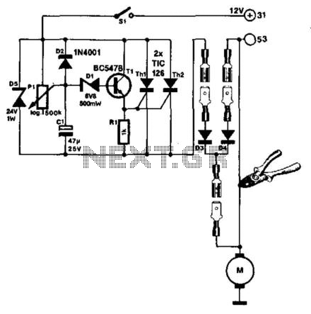
The windshield wiper interval circuit described here is compact and notable for utilizing two thyristors instead of a relay. It features only two connections and operates smoothly, even with multistage wiper circuits. The wire connecting the wiper motor to...
This shows the overall circuit diagram of the power control unit. On the left, there is a main relay controlled by the key switch. The power control unit circuit diagram illustrates the primary components and their interconnections for managing electrical...

The circuit depicted in Figure 3-49 illustrates an autotransformer that is controlled by a time relay (KT). The delay time set by the KT relay corresponds to the motor's startup duration. The circuit utilizes an autotransformer, which is a type...
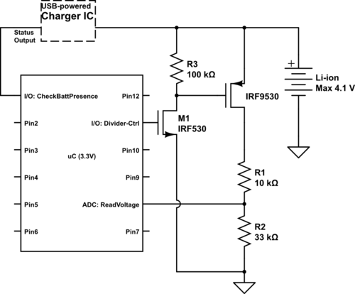
Currently using the PIC24FJ128GA010, there is a plan to utilize an Input/Output port to connect a 4.2 V LiPo battery and monitor the voltage to ensure it does not drop below 3.7 V. It is advised to avoid digital...
A circuit designed to extract and measure the modulated carrier of an infrared remote control. This circuit amplifies the entire received signal, allowing the waveform to be displayed on an oscilloscope or a frequency counter. It can measure modulation...
The objective of this project was to design a small, portable mixer powered by a 9V PP3 battery while maintaining high-quality performance. The mixer consists of three main modules that can be varied in number and/or arrangement to meet...