
Single-ended four-channel amplifier schematic
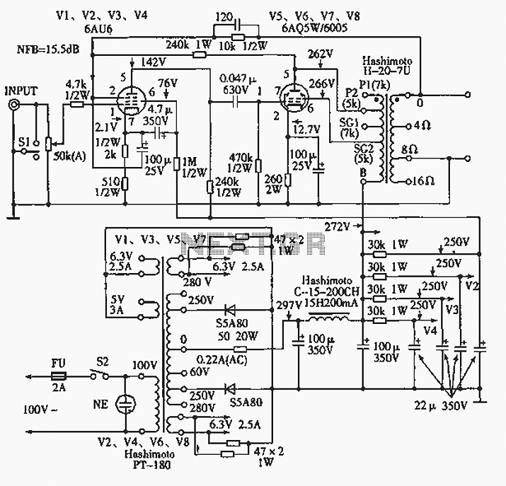
The 6AQ5W / 6005UL four-channel single-ended amplifier circuit is designed for high-fidelity audio applications, leveraging the characteristics of the 6AQ5W and 6005UL vacuum tubes to deliver rich sound quality. The circuit employs a power transformer, specifically the Tokyo Light Sound 4CP-2508-SA type 4, which is essential for stepping up the voltage during amplification. This transformer is integrated into the voltage amplification section and is crucial for achieving the desired output levels.
The volume control is facilitated by a potentiometer that adjusts the signal level across all four channels uniformly, allowing for balanced audio output. This feature is particularly beneficial in multi-channel audio systems where consistent volume levels are required across different channels.
The output stage utilizes a UL (Ultra Linear) type configuration, which enhances the amplifier's performance by improving linearity and reducing distortion. The auditory output is further refined through a dual-path negative feedback loop. The first feedback path, which incorporates a 240kΩ resistor, connects from the cathode of the tube screen output electrode back to the primary tube. This configuration introduces a feedback amount of 6dB, which helps stabilize the amplifier's gain and improve overall sound quality.
The second feedback path is derived from the output of the transformer secondary. This path provides a higher feedback amount of 9.5dB, which further contributes to the amplifier's performance by reducing distortion and enhancing frequency response. The combination of these feedback paths allows for a well-rounded audio output, making the 6AQ5W / 6005UL amplifier suitable for various audio applications where clarity and fidelity are paramount.
Overall, this circuit design exemplifies the balance between performance and functionality, making it an excellent choice for audiophiles seeking a high-quality amplification solution.6AQ5W / 6005UL four-channel single-ended amplifier circuit shown in FIG. Shown are only - channels. 4-channel system - using a power transformer for voltage amplification section uses Tokyo light sound 4CP-2508-SA type 4 with volume potentiometer while adjusting the 4 channel volume. The output stage has a good sense of hearing UL type circuit. NFB loop two routes, all the way from the cathode tube screen output electrode via 240kQ resistance to the primary tube, the amount of feedback is 6dB, another way is taken from the output of the transformer secondary 81 "1, the amount of feedback is 9.5dB.
Related Circuits
The provided description pertains to a unique low voltage variant of an audio preamp. The emitter voltage of T1 is biased close to half the supply voltage, which is 1.5V. This biasing allows for the maximum output voltage swing. The...
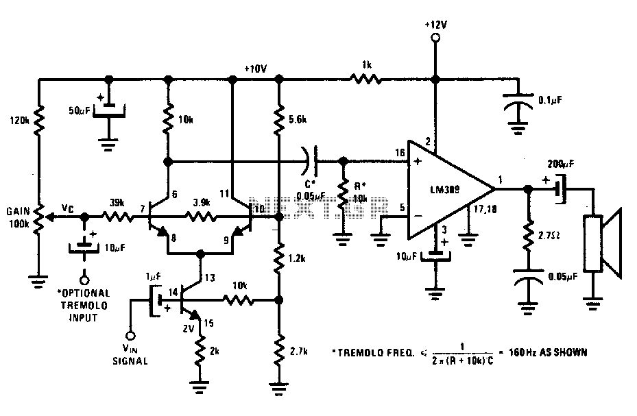
The transistors create a differential pair with an active current-source tail. This configuration, referred to as a variable-transconductance multiplier, produces an output that is proportional to the product of the two input signals. The multiplication effect arises from the...
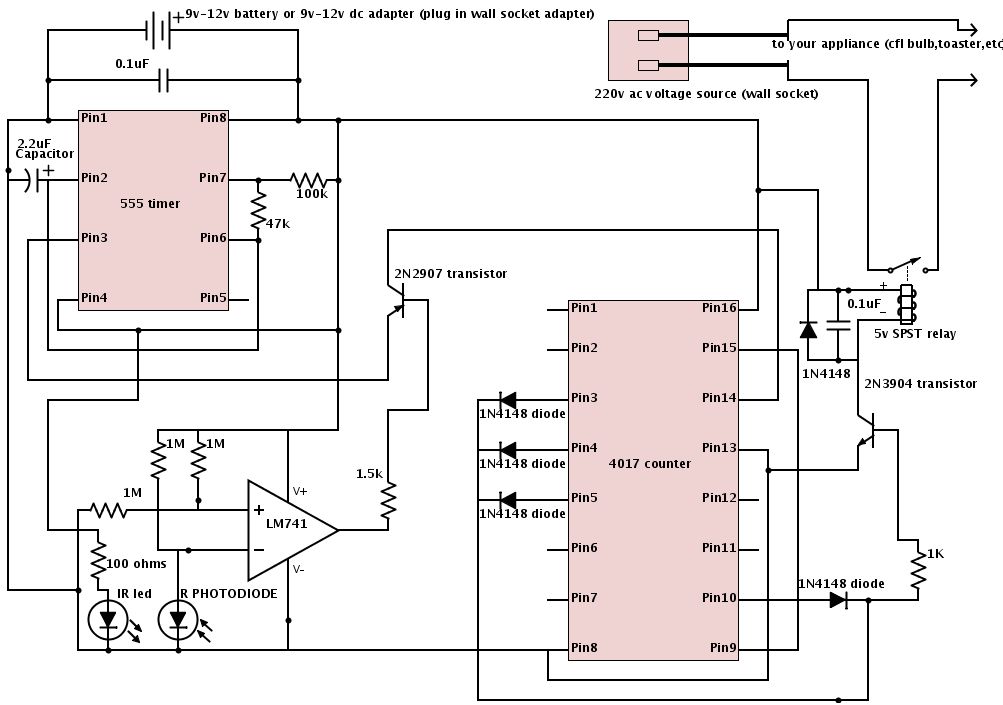
The schematic is provided below. It is recommended to construct it in three distinct sections, similar to the method demonstrated. The 555 timer circuit: connect pin 2 to pin... The schematic outlines a circuit design utilizing a 555 timer, a...
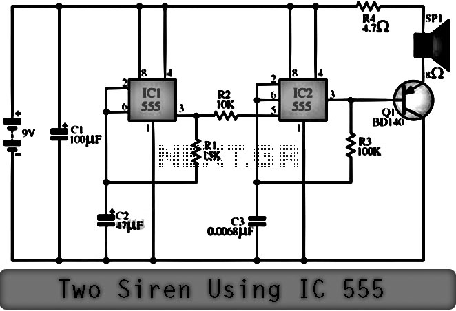
The function of the Two Siren Sound Circuit utilizing IC 555 is divided into three parts: low frequency production, manufacturing of a shrill frequency, and low frequency output. The low frequency is generated by IC1, which is connected to...
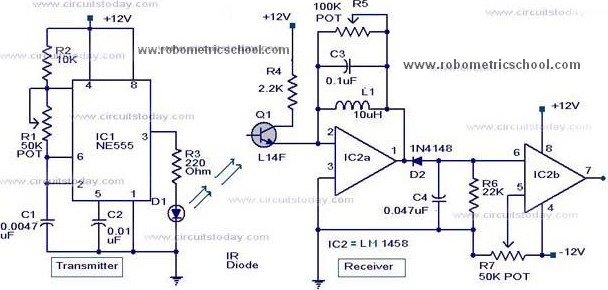
All components used in the Moving Sensor/Detector Schematic Diagram utilize the IC NE555 and the Phototransistor L14F. The primary component in this circuit is the IC NE555, along with an IR LED, the Phototransistor L14F, and the IC LM1458....
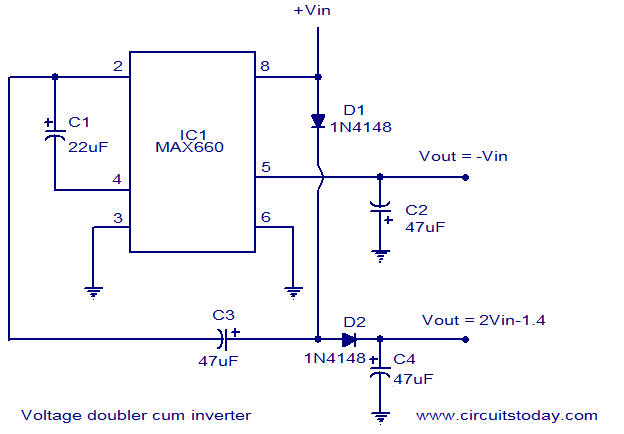
Voltage doubler circuit and voltage inverter circuit diagram with schematics using MAX660 IC, which is a DC voltage multiplier IC. This is a DC voltage doubler circuit and inverter. The MAX660 integrated circuit (IC) is designed for applications requiring a...