
Manually controlling bipolar stepper motor with Arduino and EasyDriver
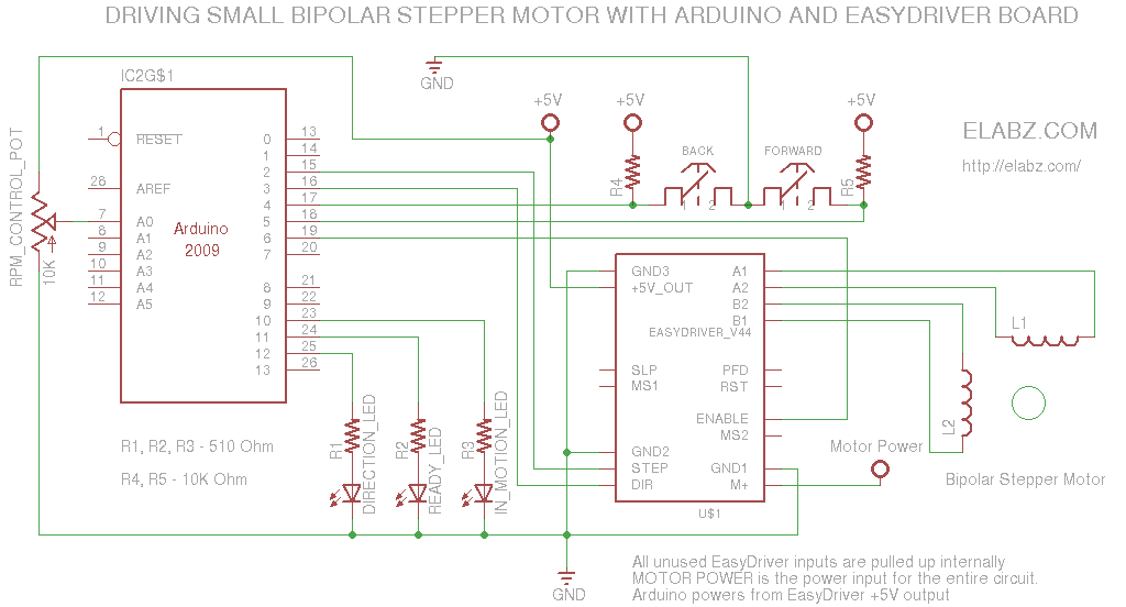
This circuit serves as a versatile tool for both testing and controlling bipolar stepper motors, which are commonly used in various applications such as robotics, CNC machines, and 3D printers. The core of the circuit typically consists of an Arduino microcontroller, which provides the necessary control signals to drive the stepper motor.
The schematic includes key components such as the stepper motor driver (e.g., A4988 or DRV8825), which interfaces between the Arduino and the stepper motor. The driver is responsible for translating the control signals from the Arduino into the appropriate voltage and current levels required to energize the motor coils.
Connections from the Arduino to the driver include step and direction pins, which determine the motor's movement and rotation direction. Additionally, the circuit may incorporate limit switches or potentiometers for manual control and positioning, allowing for more precise adjustments during testing.
Power supply considerations are crucial, as the stepper motor requires a specific voltage and current rating to operate effectively. A suitable power source should be selected based on the motor specifications, ensuring that the driver can handle the load without overheating or damaging the components.
The Arduino sketch typically includes libraries that facilitate the control of the stepper motor, providing functions for setting speed, acceleration, and the number of steps to move. This software component is essential for executing the desired movements and testing the motor's functionality.
Overall, this circuit is an effective solution for users seeking to test and control bipolar stepper motors, offering both hardware schematics and software support to streamline the development process.A simple circuit that can be used for testing of bipolar stepper motors or for manual positioning using steppers. Schematics, Arduino sketch and video here 🔗 External reference
Related Circuits
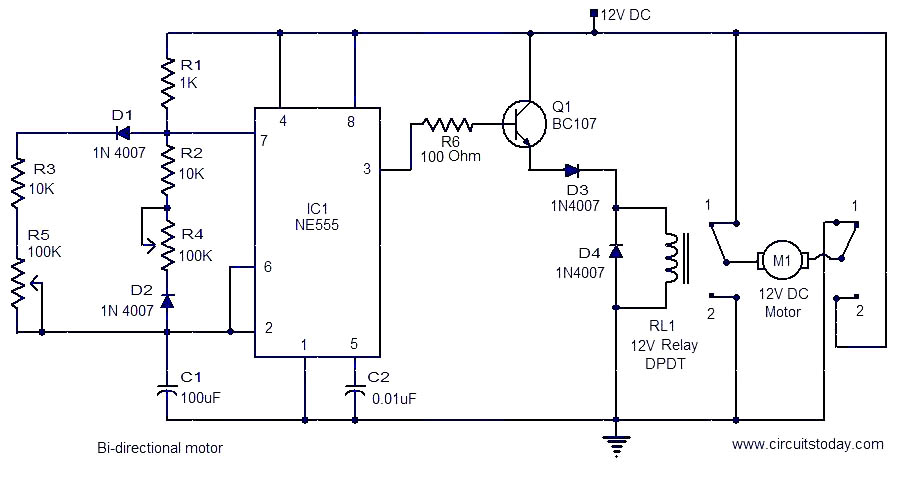
This is a simple and easy-to-construct circuit designed to provide a bidirectional drive for a DC motor. The circuit operates straightforwardly. The output of an astable multivibrator based on IC1 (NE555) is utilized to control the relay RL1 that...
Two simple 12V DC motor speed controllers can be constructed for a minimal cost. These controllers take advantage of the principle that the rotational speed of a DC motor... DC motor speed controllers are essential components in various applications where...
A two-phase servo motor features a field winding and a control winding. When there is a 90° phase difference between the two, it generates rotational torque. A potentiometer connected to the motor shaft measures the voltage difference between the...
The circuit is designed to enable rapid changes in motor speed and direction by utilizing four outputs to drive a MOSFET H-bridge. The lower rail power MOSFETs are N-channel devices, while the upper rail MOSFETs are P-channel. All MOSFETs...
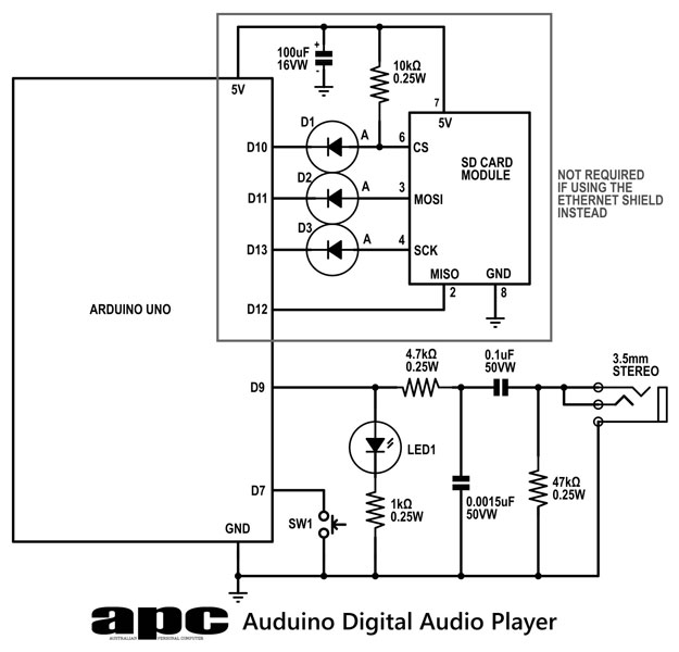
In this series, a diverse exploration of how Arduino interacts with various real-world devices has been presented, from servo motors to ultrasonic range finders, TVs to humidity sensors. The focus now shifts to generating sound using Arduino. The project...
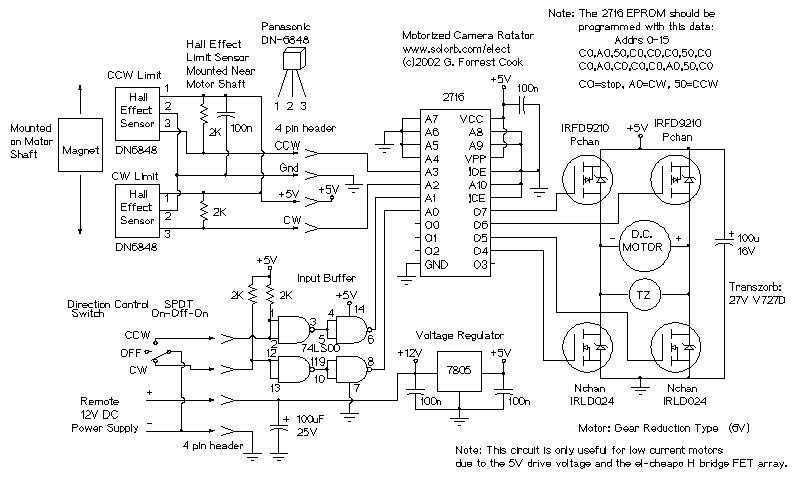
The camera rotator circuit uses a 2716 EPROM to store a table of logic values that control the motor driver (H-bridge) circuit. The EPROM data is shown in the schematic. By using the EPROM, a large number of discrete...