
supernode dependent voltage source

The described circuit involves a network of nodes and voltage sources, where the top right node serves as a critical point for voltage determination. The connection of two voltage sources to this node suggests that it plays a pivotal role in the overall voltage distribution within the circuit. Each node in the circuit contains three elements, which may include resistors, capacitors, or inductors, contributing to the overall functionality and behavior of the circuit.
By selecting the top right node, the voltages at adjacent nodes can be inferred, enabling a systematic approach to analyzing the circuit. The reference node, typically grounded, establishes a common potential against which all other node voltages are measured. This method simplifies the analysis by reducing the number of unknowns and allowing for the application of Kirchhoff's Voltage Law (KVL) to the circuit.
Once the node voltages are calculated, the next step involves assessing the power associated with each voltage source. The power (P) delivered by a voltage source can be computed using the formula P = V * I, where V is the voltage across the source and I is the current flowing through it. It is essential to adhere to the passive sign convention when determining the direction of current flow, ensuring that it enters through the positive terminal of the voltage source. This convention is crucial for accurate power calculations, as it dictates the sign of the power value, indicating whether the source is supplying or absorbing power.
In summary, the circuit analysis begins with the identification of a pivotal node connected to voltage sources, leading to the determination of node voltages. Following this, the power calculations for the voltage sources are conducted, adhering to the passive sign convention to ensure accurate results. This structured approach provides a clear pathway for understanding the behavior of the circuit and the interactions between its components.The right top node is connected to two voltage sources and has three elements. All other nodes also have three elements. Hence, we select the right top node because by this selection, we already know the node voltages of two other nodes, i. e. the ones that the reference node is connected to them by voltage sources. All node voltages are determined . Now, the power of voltage sources can be calculated from the node voltages. For each source, we need to find the voltage across the source as well as the current flowing through it to compute the power. . However, the comply with the passive voltage convention, the current should be entering from the positive terminal of the defined voltage as shown below.
Therefore, 🔗 External reference
Related Circuits
PIC C Compilers are utilized to compile source code, leveraging the extensive built-in functions offered by these compilers. A single C statement can produce multiple pages of PIC RISC instructions, eliminating the need for manual coding. CCS charges $125...
It is often necessary to configure a voltage regulator integrated circuit (IC) to provide a higher output voltage than that established by the regulator alone. One method to achieve this is by connecting the common terminal to the midpoint...

This is a simple design for a voltage regulator circuit using a pass transistor. The design is built around the LM317T. The output current of the LM317T can be increased by incorporating an additional power transistor to share a...
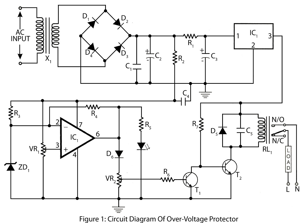
An Over Voltage Protector is a straightforward circuit designed to safeguard appliances from excessive voltage. It includes a circuit diagram and a parts list for various electronics projects related to over voltage protection. The Over Voltage Protector circuit typically employs...
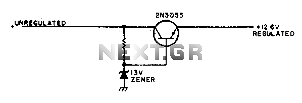
This simple mobile voltage regulator circuit may save your two-meter or CB transceiver if the voltage regulator fails. The 2N3055 should be heat-sinked if the current drawn by the rig exceeds 2 A during transmission. This circuit will do...
The technical parameters of high-speed optocouplers include a rise time (t1) of less than or equal to 300 ns, a circuit transfer ratio (CTR) of 50%, an isolation voltage (VSO) of at least 15,000 V, and an output transistor...