
water pump relay controller circuit schematic
The circuit operates on a simple principle of level detection using two sensors, which are strategically positioned at different heights within the water reservoir. The shorter sensor is designed to detect when the water level is sufficiently high, while the longer sensor detects when the water level is critically low.
The integrated circuit (IC1C) plays a crucial role in processing the signals from the sensors. It monitors the state of the sensors continuously. When the water level drops below the longer sensor, the output at pin #10 of IC1C goes low, indicating a low water condition. This state is maintained until the water rises to the level of the longer sensor. Once the water touches the longer sensor, the output remains low until the shorter sensor is activated, indicating that the water level is adequate.
When the shorter sensor is activated, the output of IC1C transitions to high. This change in state triggers transistor Q1 to conduct. Q1 acts as a switch, allowing current to flow to the relay coil. The relay, once energized, closes its contacts and powers the water pump, which begins to fill the reservoir or well.
The relay is an essential component in this circuit as it provides electrical isolation between the low-voltage control circuit and the high-voltage water pump circuit. This ensures safe operation and prevents damage to sensitive electronic components.
Additionally, the circuit may include protective features such as diodes to prevent back EMF from the relay coil from damaging the circuit components when the relay is de-energized. Proper sizing of the relay and pump according to the application requirements is also critical to ensure efficient operation of the system.
In summary, this automatic water level control circuit effectively manages the operation of a water pump based on predetermined water levels, ensuring that the reservoir or well maintains an appropriate water supply without manual intervention.By means of a Relay, employed to drive a water pump, this circuit provides automatic level control of a water reservoir or well. The shorter steel rod is the ""water high"" sensor, whereas the longer is the ""water low"" sensor. When the water level is below both sensors, IC1C output (pin #10) is low; if the water becomes in contact with the longer sensor the output remains low until the shorter sensor is reached.
At this point IC1C output goes high, Q1 conducts, the Relay is energized and the pump starts operating.. 🔗 External reference
Related Circuits
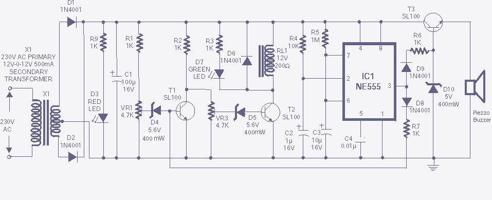
The high and low voltage cut-off with delay and alarm circuit, along with its circuit diagram, is explained in this post. The high and low voltage cut-off circuit is designed to protect electrical devices from damage caused by excessive voltage...
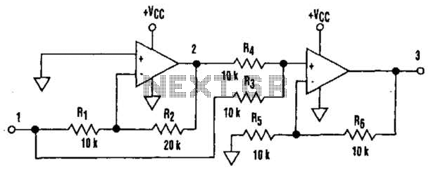
It is well understood that utilizing single-supply operational amplifiers (op amps) can present challenges when implementing simple functions in a bipolar signal environment. Often, this necessitates the use of additional op amps and other electronic components. Considering this, it...

The following method allows the timer to be triggered by a normally closed switch. This would be useful in applications such as intrusion alarms where the protection circuit is broken if a window or door is opened. Trigger Input...
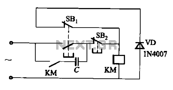
An AC contactor switch, when used with DC or pulse DC excitation, can minimize short circuit and core power consumption. This results in a significant reduction in the power consumption of the electromagnet, which can eliminate noise and reduce...
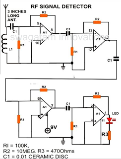
A simple electronic circuit project is presented that can be constructed by any school student for display at a school science fair. The proposed circuit is a high-gain operational amplifier (op-amp) amplifier designed to detect the slightest RF disturbances...
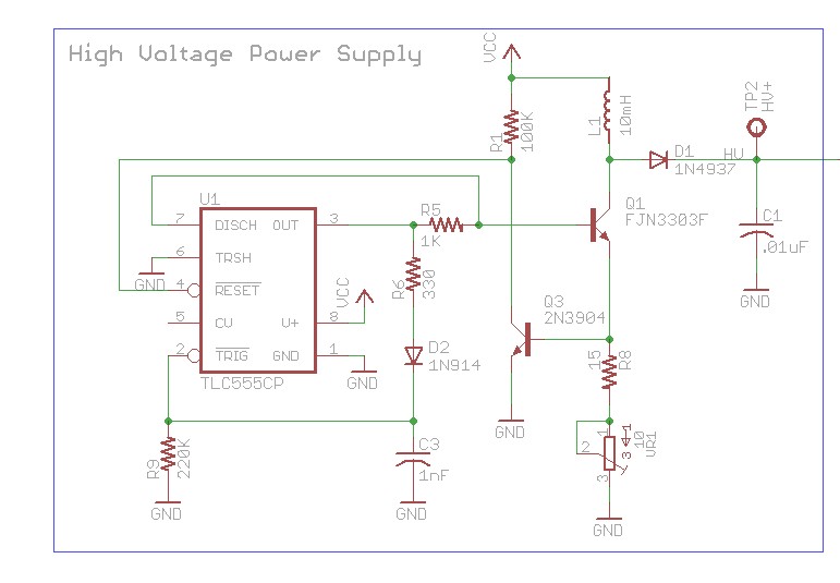
The design involves using a 555 timer as an oscillator in the high voltage power supply section. There is a query regarding the possibility of altering the design to utilize an output from a microcontroller to generate an oscillating...