
Free Running Oscillator Circuit

The described circuit operates in astable mode, which means it continuously oscillates between high and low states without requiring any external triggering. The 555 timer IC is a versatile component that can be configured in various modes, with astable operation being one of the most common applications. In this configuration, the timer generates a square wave output, which can be utilized for various applications such as clock pulses, tone generation, or LED flashing.
In the circuit, the timing interval is determined by the values of resistors Ra and Rb, as well as the capacitance of capacitor C. The frequency of oscillation (f) can be calculated using the formula:
\[ f = \frac{1.44}{(Ra + 2Rb)C} \]
This equation shows that the frequency is inversely proportional to the total resistance and the capacitance. Therefore, selecting appropriate values for Ra, Rb, and C is crucial for achieving the desired frequency of oscillation.
The 555 timer operates by charging and discharging the capacitor through the resistors. Initially, when the circuit is powered, capacitor C begins charging through Ra and Rb. As the voltage across C reaches 2/3 V+, the 555 timer's internal comparator triggers the discharge pin (pin 7), which connects C to ground, allowing it to discharge rapidly. The capacitor's discharge causes the output (pin 3) to go low, and the cycle repeats as the capacitor charges again.
Utilizing a CMOS version of the 555 timer can enhance the circuit's performance by providing lower power consumption, reduced voltage spikes, and higher frequency capabilities. This makes it suitable for battery-operated devices or applications where power efficiency is paramount.
In summary, this astable oscillator circuit using a 555 timer IC is a simple yet effective design for generating continuous square wave signals. Proper selection of component values is essential for achieving the desired oscillation frequency while ensuring reliable operation within the specified limits of the 555 timer IC.This is a circuit for oscillator using astable mode operation. The basic oscillatior is using 555 timer IC. This circuit is also give mode free running oscillator. This is the figure of the circuit. Operation of the circuit is begin, when initialy by capacitor C charged towards 2/3 V+ with Ra and Rb. When voltage on C reaches that threshold level, the discharge output in pin 7 is turning on to discharging C. Using CMOS 555 timer IC is a very wide frequency at very low of voltage spikes and dissipation can be achieved. Selections of values the Ra and Rb is limited by input leakage specification at time in pin 7, 2, and 6.
🔗 External reference
Related Circuits
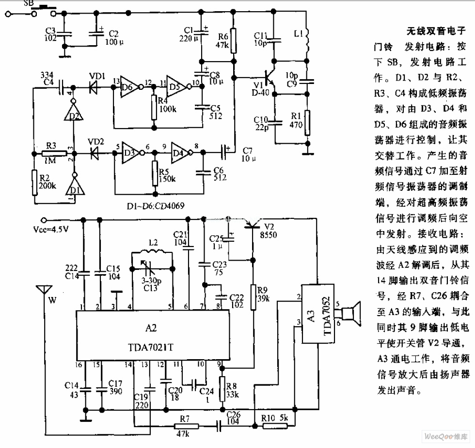
The transmitter circuit is activated by pressing the SB button. Components D1, D2, R2, R3, and C4 form a low-frequency oscillator that controls an audio oscillator made up of D3, D4, D5, and D6, allowing them to operate alternately....
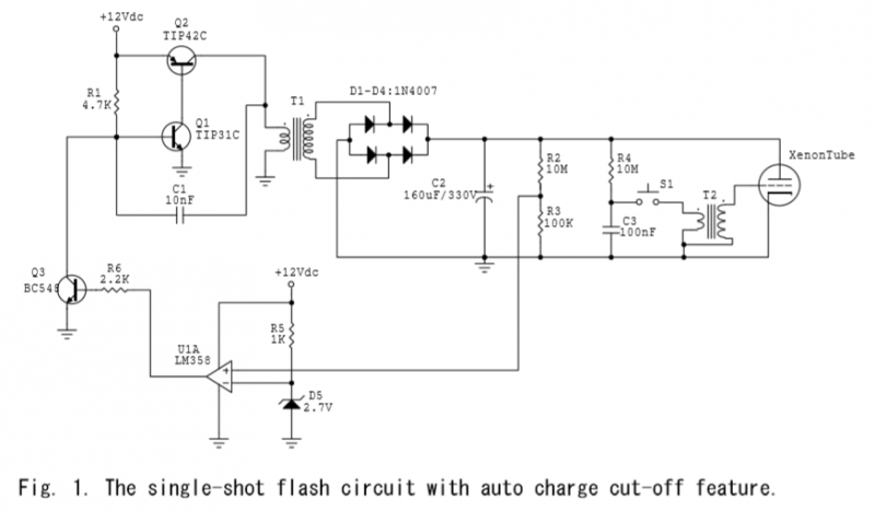
A voltage divider is created using resistors R2 (10MΩ) and R3 (100KΩ), which effectively reduces the voltage across capacitor C2 by a factor of approximately 100. The ground of C2 is connected to the inverter ground for reference. An...

This field strength meter consists of a tuned crystal detector that generates a DC output voltage from a transmitted signal. The DC voltage is utilized to modulate the frequency of a transmitter with a power output of 100 mW,...
This process can be simplified by utilizing a display kit from PJRC, which includes the appropriate firmware installed on the display, a functioning pushbutton board, and the necessary cables. The PJRC display features a 4-pin connector compatible with the...
Most CD-ROMs available have an audio output that allows for the connection of headphones or an amplifier. This circuit enables the use of the CD-ROM as a standalone audio CD player without requiring a computer. The circuit essentially functions...
The system involves positioning a small magnet near the stalk switch SW1, which is connected to the hand or garments of the individual carrying the bag via a tiny cable. Due to the compact nature of the circuit, it...