
Frequency counter BNC input schematic

The described circuit functions as a robust input interface suitable for both CMOS and TTL logic families. The incorporation of over-voltage and under-voltage protection ensures that the circuit can withstand voltage levels beyond its specified operating range, thus safeguarding downstream components from potential damage.
Schmitt triggers are a critical component in this design, providing hysteresis that enhances the circuit's tolerance to noisy signals and allows for reliable operation even when input signals have slow rise and fall times. This feature is particularly beneficial in high-speed applications where signal integrity can be compromised by slow transitions.
The circuit's capability to operate at frequencies up to 30 MHz indicates that it can be effectively used in high-speed digital applications, making it suitable for interfacing with various sensors, microcontrollers, and communication devices.
For implementation, the design may include a series of resistors and capacitors to set the appropriate time constants for the Schmitt trigger inputs, ensuring optimal performance. Additionally, careful consideration should be given to the selection of input protection components, such as transient voltage suppressors (TVS) or zener diodes, to effectively clamp any excessive voltage levels while minimizing signal distortion.
Overall, this circuit design represents a versatile solution for applications requiring reliable logic level interfacing with inherent protection features and high-speed performance capabilities.This is a CMOS-compatible (and hopefully also TTL) input featuring over- and under-volatage protection. Schmitt triggers are used to allow for input with long transition times. Verified to work up to 30MHz. 🔗 External reference
Related Circuits
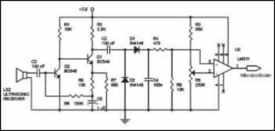
Ultrasonic receivers detect an ultrasonic signal emitted by an ultrasonic transmitter at a specific frequency. The received signal is filtered using a band-pass filter circuit that allows only the predetermined frequency range to pass. The output signal is then...
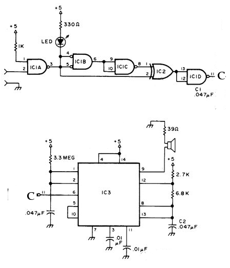
The circuit was designed to create a frequency generator that consists of seven steps during operation. It includes a crystal oscillator, which is an electronic circuit made of... The frequency generator circuit operates through a series of seven distinct steps,...
The electronic counter of the winding machine utilizes an LED digital display to indicate the number of turns of the wound coil, with a maximum counting capacity of 9900 turns. The operational principle of the winding machine circuit consists...
The NE556 timer can function as an indicator for the static state of a digital logic audible terminal. An audible logic probe is beneficial for visually inspecting a component while simultaneously checking the logic state at another point far...
This power supply unit (PSU) has been designed for high-current ham radio transceivers, providing approximately 20 Amps at 13.8V. It features a secondary output capable of handling currents from 15 mA up to a maximum of 20A. The unit...
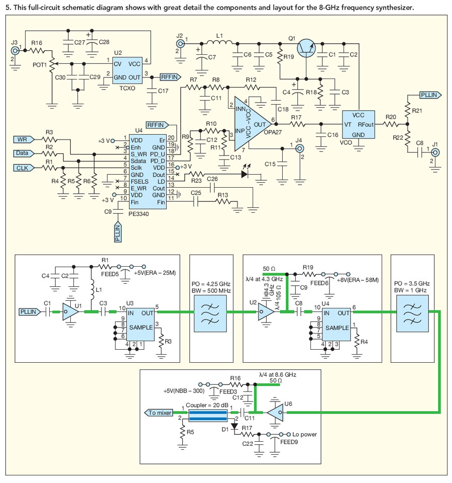
By developing a low-noise frequency synthesizer at 2 GHz and applying a pair of doublers, it is possible to achieve low-phase-noise outputs past 8 GHz for digital microwave radios. The design of a low-noise frequency synthesizer operating at 2 GHz...
Warning: include(partials/cookie-banner.php): Failed to open stream: Permission denied in /var/www/html/nextgr/view-circuit.php on line 713
Warning: include(): Failed opening 'partials/cookie-banner.php' for inclusion (include_path='.:/usr/share/php') in /var/www/html/nextgr/view-circuit.php on line 713