
Frequency Generator Counter
The functional generator described utilizes the MAX038 integrated circuit, which is well-regarded for its precision in generating various waveforms. The device is capable of producing stable sine, triangular, and square waves across a significant frequency range, making it versatile for a variety of applications in electronics testing and experimentation.
The PIC16F877 microcontroller serves as the control unit, enabling complex functions through its multiple input/output capabilities. This microcontroller facilitates the selection of waveforms, frequency adjustments, and the management of data display on the LCD. The use of a switching capacitor allows for precise frequency generation, enhancing the accuracy of the output signals.
The design emphasizes the importance of proper PCB preparation, with an emphasis on avoiding common mistakes during the assembly process. The initial testing phase, conducted without an enclosure, allows for easy troubleshooting and verification of functionality before final assembly.
Upon successful verification of the circuit's operation, the device is then housed within a protective casing. The mechanical processing steps, including drilling and CNC engraving, are crucial for creating a professional appearance and ensuring user-friendly access to controls and display.
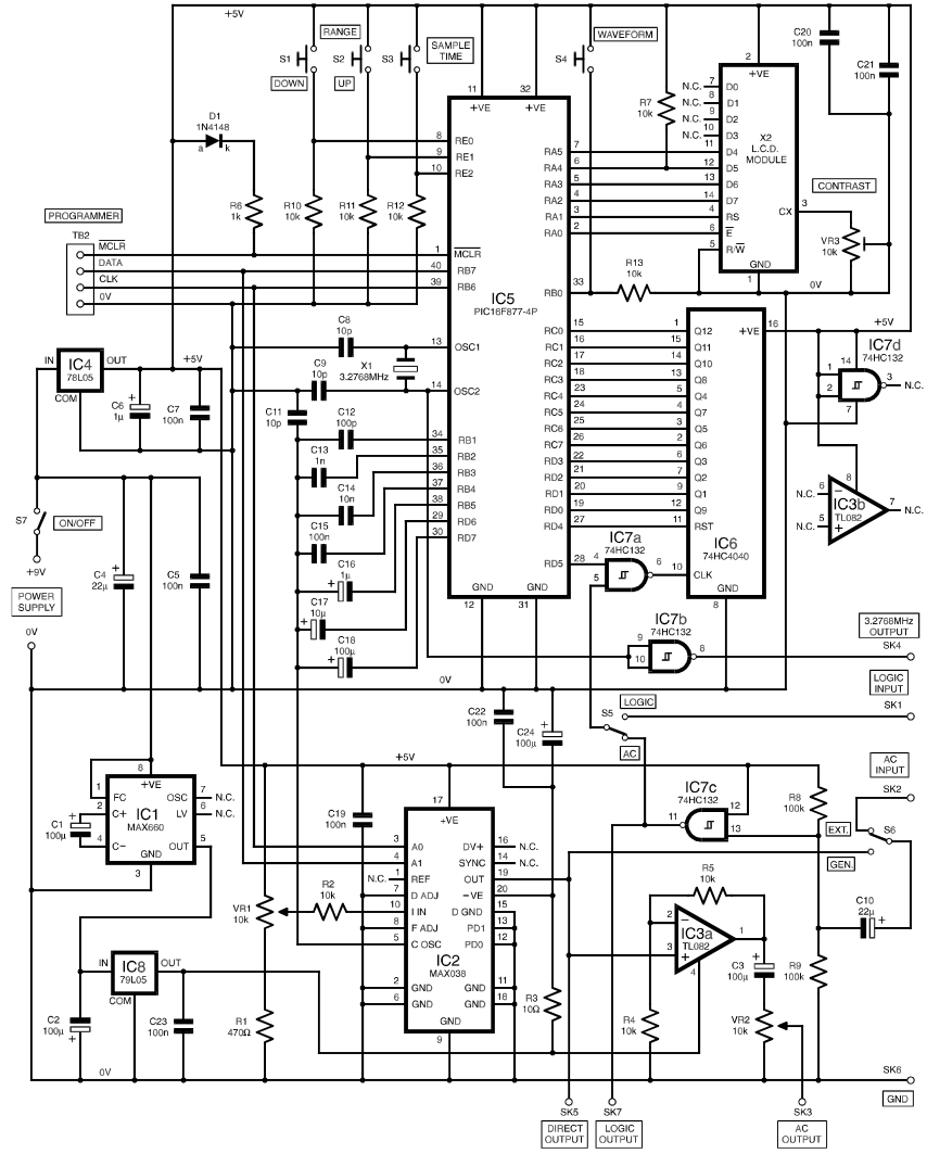
The generator's user interface is designed for simplicity, featuring a single-button operation that allows users to easily navigate through the frequency range and waveform options. The inclusion of independent amplitude adjustment and phase-shifting capabilities further enhances the functionality of the device, making it suitable for a range of experimental and practical applications in electronics.The functional generator is a device that would have any better equipped electronic lab should have a not so frequently used gadgets, but when you need it, we certainly appreciate its convenience. Here is the procedure of the scheme, which was published in the magazine Everyday Practical Electronics 2000g nr.
07. The heart of this device i s an integrated circuit MAX038 precision function generator that is adjustable for a triangular, square, or sine wave signal. Frequency range is quite wide from 1Hz to 10MHz. PIC16F877 microcontroller control circuit with five inputs/outputs which is essential for several functions.
Used to switching capacitor to generate the frequency, the choice of waveform, frequency calculations and data display on the LCD. In preparing the pcb by PDF files that are attached, it is important to pay attention to a mistake that I made and is shown below.
After programming the PIC and all the components have been soldiered, at first is checking the validity with no case, just naked electronics. There is a photo of The LCD shows that everything is going according to plan. Nice to see that everything was planned is in right place. The next step is a process in which we will put in the housing, then follows the fun with tools for mechanical processing, drilling and CNC engraving job to the front panel.
It is willingly arranged by my friend that owed me the favour, I am only reminded him that I wouldn`t forbid the pleasure of his participating in this venture. Management of one button, frequency span 0, 1Hz-10MHz, sinusoidal, triangular, rectangular, independent adjustment of porosity, indication on LCD, external CCP and frequency modulation, non-volatile memory, the generator of the fluctuations shifted on 90 degrees,
🔗 External reference
Related Circuits
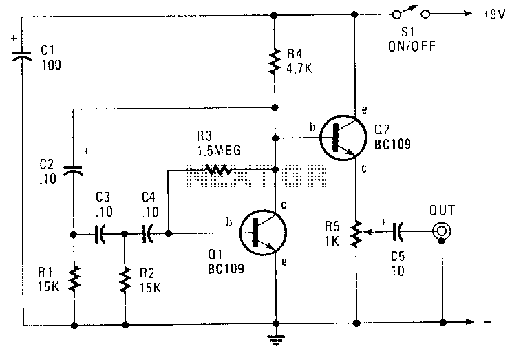
This circuit generates a sinusoidal output of approximately 8 V peak-to-peak, which can be adjusted down to zero, operating at a frequency of about 500 Hz. The signal is produced by a phase-shift oscillator. The described circuit utilizes a phase-shift...
The NI 655X is a versatile high-speed digital product capable of interfacing with various technologies. This application note illustrates how to connect the NI 655X to Low Voltage Differential Signaling (LVDS) devices. LVDS is an emerging differential digital standard...
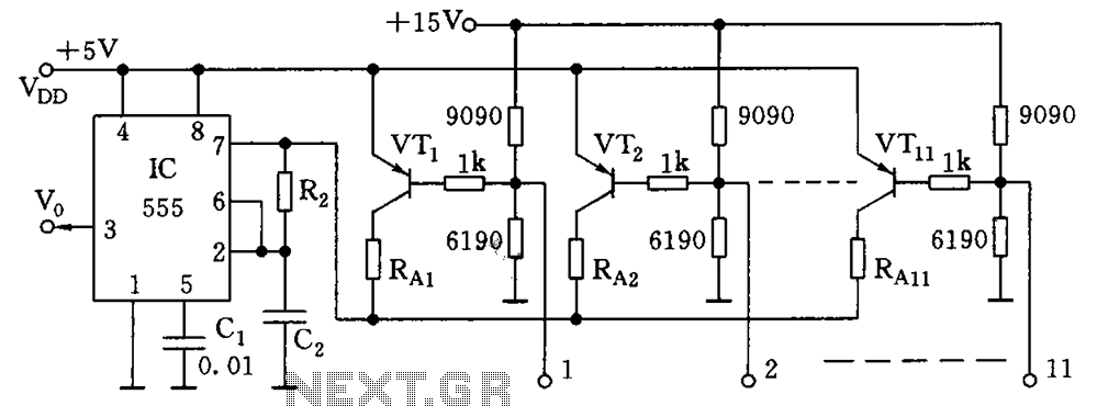
As illustrated in the figure, the base bias circuit for transistors VT1 to VT11 is designed to accept binary data, where a high level represents 1 and a low level represents 0. This configuration allows for 2048 combinations of...
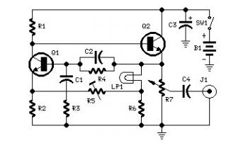
Set R5 to read 1V RMS on an audio millivoltmeter connected to the output with R7 rotated fully clockwise, or to view a sine wave of 2.828V peak-to-peak amplitude on the oscilloscope. An audio amplifier is an electronic device...
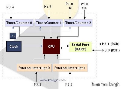
The diagram below illustrates a simplified representation of the main peripherals present in the 89S52 microcontroller, which is part of the 8052/8051 family. The 89S52 includes three Timers/Counters. The term "Timer/Counter" is applicable because this unit can function either...
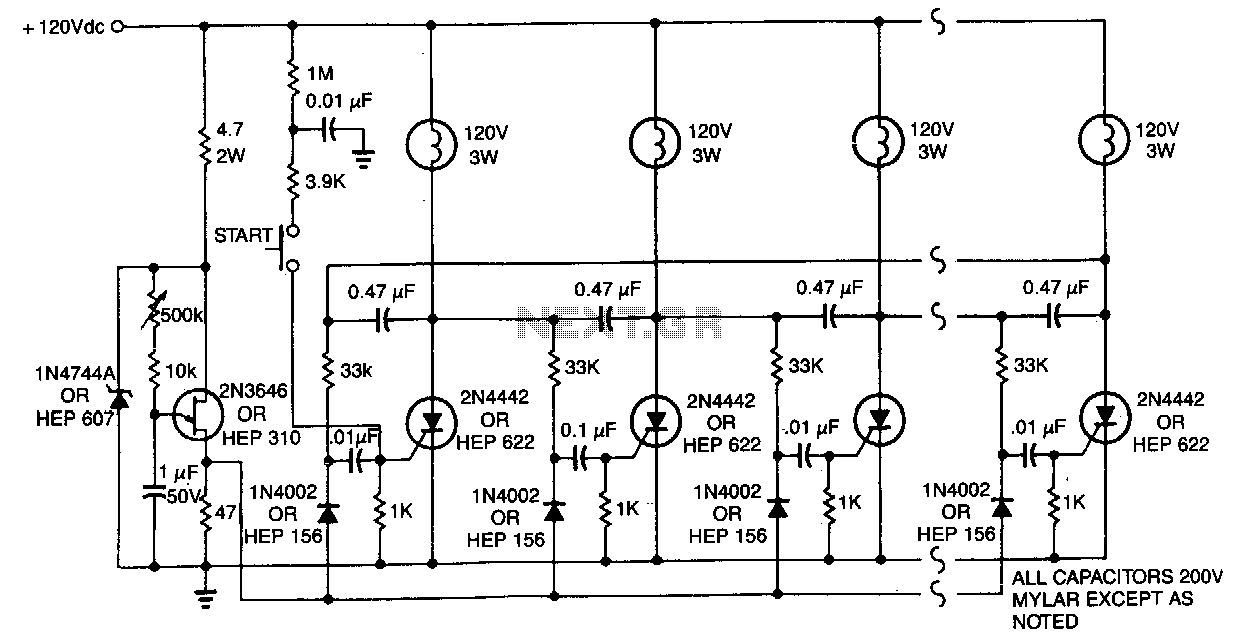
One lamp at a time is lit in the string to give the appearance of a moving point of light. More: The ring counter circuit. The described circuit utilizes a ring counter configuration to create a sequential lighting effect in...